Infiniti QX4 (R50). Manual - part 75
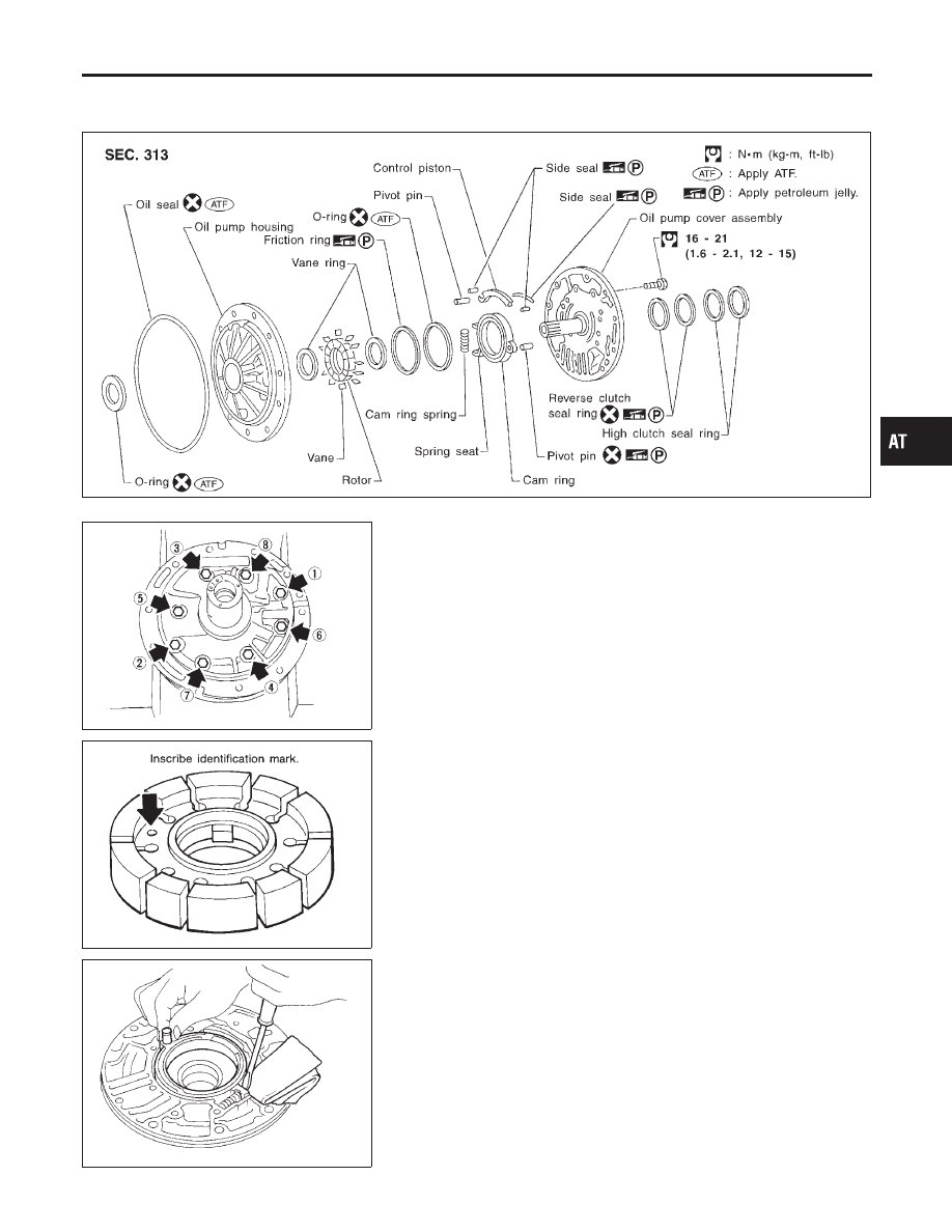
Oil Pump
COMPONENTS
NBAT0112
SAT648AB
SAT649A
DISASSEMBLY
NBAT0113
1.
Loosen bolts in numerical order and remove oil pump cover.
SAT650A
2.
Remove rotor, vane rings and vanes.
I
Inscribe a mark on back of rotor for identification of fore-
aft direction when reassembling rotor. Then remove rotor.
SAT651A
3.
While pushing on cam ring remove pivot pin.
I
Be careful not to scratch oil pump housing.
GI
MA
EM
LC
EC
FE
TF
PD
AX
SU
BR
ST
RS
BT
HA
SC
EL
IDX
REPAIR FOR COMPONENT PARTS
Oil Pump
AT-297