Infiniti QX4 (R50). Manual - part 30
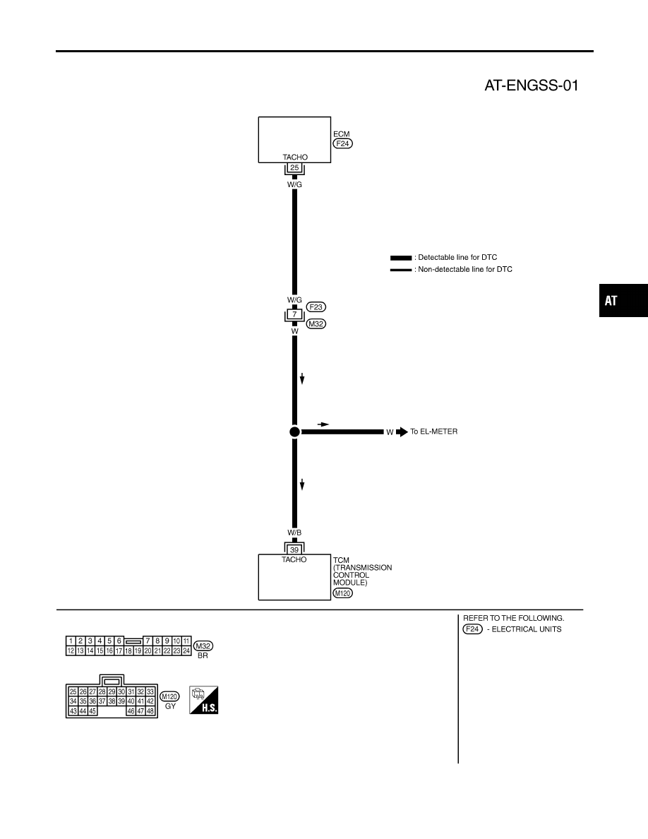
Wiring Diagram — AT — ENGSS
NBAT0189
MAT911A
GI
MA
EM
LC
EC
FE
TF
PD
AX
SU
BR
ST
RS
BT
HA
SC
EL
IDX
DTC P0725 ENGINE SPEED SIGNAL
Wiring Diagram — AT — ENGSS
AT-117
|
|
|
Wiring Diagram — AT — ENGSS NBAT0189 MAT911A GI MA EM LC EC FE TF PD AX SU BR ST RS BT HA SC EL IDX DTC P0725 ENGINE SPEED SIGNAL Wiring Diagram — AT — ENGSS AT-117 |