Infiniti QX4 (R50). Manual - part 28


  Index      Infiniti     Infiniti QX4 (R50) - service repair manual 2001 year


Search            copyright infringement  


Content   ..  26  27  28  29   ..


Infiniti QX4 (R50). Manual - part 28


4

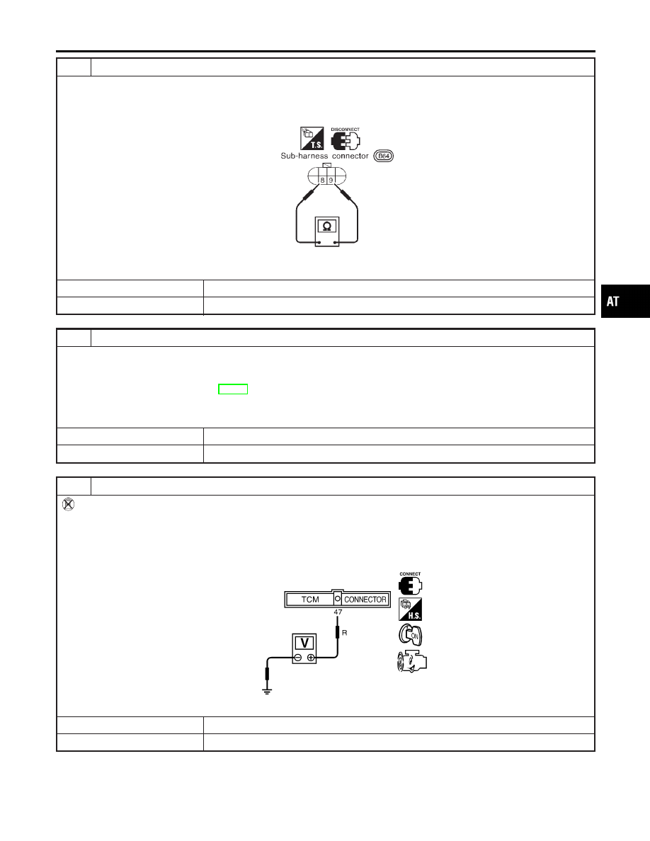
CHECK A/T FLUID TEMPERATURE SENSOR WITH TERMINAL CORD ASSEMBLY

1. Turn ignition switch to “OFF” position.
2. Disconnect terminal cord assembly connector on the right side of transfer assmebly.
3. Check resistance between terminals 8 and 9 when A/T is cold [20°C (68°F)].

SAT697I

Is resistance approx. 2.5 k

?

Yes

©

GO TO 7.

No

©

GO TO 5.

5

DETECT MALFUNCTIONING ITEM

1. Remove oil pan.
2. Check the following items:

I

A/T fluid temperature sensor
Refer to “Component Inspection”, AT-110.

I

Harness of terminal cord assembly for short or open

OK or NG

OK

©

GO TO 7.

NG

©

Repair or replace damaged parts.

6

CHECK INPUT SIGNAL OF A/T FLUID TEMPERATURE SENSOR (WITHOUT CONSULT-II)

Without CONSULT-II

1. Start engine.
2. Check voltage between TCM terminal 47 and ground while warming up A/T.

Voltage:

Cold [20°C (68°F)]

Hot [80°C (176°F)]:

Approximately 1.5V

0.5V

SAT518J

OK or NG

OK

©

GO TO 4.

NG

©

GO TO 3.

GI

MA

EM

LC

EC

FE

TF

PD

AX

SU

BR

ST

RS

BT

HA

SC

EL

IDX

DTC P0710 A/T FLUID TEMPERATURE SENSOR CIRCUIT

Diagnostic Procedure (Cont’d)

AT-109

7

CHECK DTC

Perform Diagnostic Trouble Code (DTC) confirmation procedure, AT-106.

OK or NG

OK

©

INSPECTION END

NG

©

GO TO 8.

8

CHECK TCM INSPECTION

1. Perform TCM input/output signal inspection.
2. If NG, recheck TCM pin terminals for damage or loose connection with harness connector.

OK or NG

OK

©

INSPECTION END

NG

©

Repair or replace damaged parts.

SAT687I

Component Inspection

NBAT0033

A/T FLUID TEMPERATURE SENSOR

NBAT0033S01

I

For removal, refer to AT-273.

I

Check resistance between terminals 8 and 9 while changing
temperature as shown at left.

Temperature °C (°F)

Resistance

20 (68)

Approximately 2.5 k

80 (176)

Approximately 0.3 k

DTC P0710 A/T FLUID TEMPERATURE SENSOR CIRCUIT

Diagnostic Procedure (Cont’d)

AT-110

SAT136K

Description

NBAT0034

The revolution sensor detects the revolution of the out put shaft
parking pawl lock gear and emits a pulse signal. The pulse signal
is sent to the TCM which converts it into vehicle speed.

TCM TERMINALS AND REFERENCE VALUE

NBAT0034S02

Remarks: Specification data are reference values.

Terminal

No.

Wire color

Item

Condition

Judgement

standard

(Approx.)

29

W

Revolution sensor
(Measure in AC
range)

When vehicle cruises at 30 km/h (19 MPH).

1V or more
Voltage rises
gradually in
response to
vehicle speed.

When vehicle parks.

0V

42

B

Throttle position
sensor
(Ground)

0V

ON BOARD DIAGNOSIS LOGIC

NBAT0034S03

Diagnostic trouble code

Malfunction is detected when ...

Check item (Possible cause)

: VEH SPD SEN/CIR AT

TCM does not receive the proper voltage
signal from the sensor.

I

Harness or connectors
(The sensor circuit is open or shorted.)

I

Revolution sensor

: P0720

GI

MA

EM

LC

EC

FE

TF

PD

AX

SU

BR

ST

RS

BT

HA

SC

EL

IDX

DTC P0720 VEHICLE SPEED SENSOR·A/T (REVOLUTION SENSOR)

Description

AT-111

SAT014K

SAT971J

SAT014K

SAT020K

DIAGNOSTIC TROUBLE CODE (DTC) CONFIRMATION
PROCEDURE

NBAT0034S01

CAUTION:

I

Always drive vehicle at a safe speed.

I

Be careful not to rev engine into the red zone on the
tachometer.

NOTE:
If “DIAGNOSTIC TROUBLE CODE CONFIRMATION PROCE-
DURE” has been previously conducted, always turn ignition
switch “OFF” and wait at least 5 seconds before conducting
the next test.
After the repair, perform the following procedure to confirm the
malfunction is eliminated.

With CONSULT-II

1)

Turn ignition switch “ON” and select “DATA MONITOR” mode
for “A/T” with CONSULT-II.

2)

Drive vehicle and check for an increase of “VHCL/S SE·MTR”
value.
If the check result is NG, go to “DIAGNOSTIC PROCEDURE”,
AT-200.
If the check result is OK, go to following step.

3)

Select “DATA MONITOR” mode for “ENGINE” with CONSULT-
II.

4)

Start engine and maintain the following conditions for at least
5 consecutive seconds.
VHCL SPEED SE: 30 km/h (19 MPH) or more
THRTL POS SEN: More than 1.2V
Selector lever: D position (OD “ON”)
Driving pattern: Driving the vehicle uphill (increased engine
load) will help maintain the driving conditions required for this
test.
If the check result is NG, go to “DIAGNOSTIC PROCEDURE”,
AT-114.
If the check result is OK, go to following step.

5)

Maintain the following conditions for at least 5 consecutive
seconds.
CMPS·RPM (REF): 3,500 rpm or more
THRTL POS SEN: More than 1.2V
Selector lever: D position (OD “ON”)
Driving pattern: Driving the vehicle uphill (increased engine
load) will help maintain the driving conditions required for this
test.

With GST

Follow the procedure “With CONSULT-II”.

DTC P0720 VEHICLE SPEED SENSOR·A/T (REVOLUTION SENSOR)

Description (Cont’d)

AT-112


Content   ..  26  27  28  29   ..