Infiniti QX4 (R50). Manual - part 5


  Index      Infiniti     Infiniti QX4 (R50) - service repair manual 2001 year


Search            copyright infringement  


Content   ..  3  4  5  6   ..


Infiniti QX4 (R50). Manual - part 5


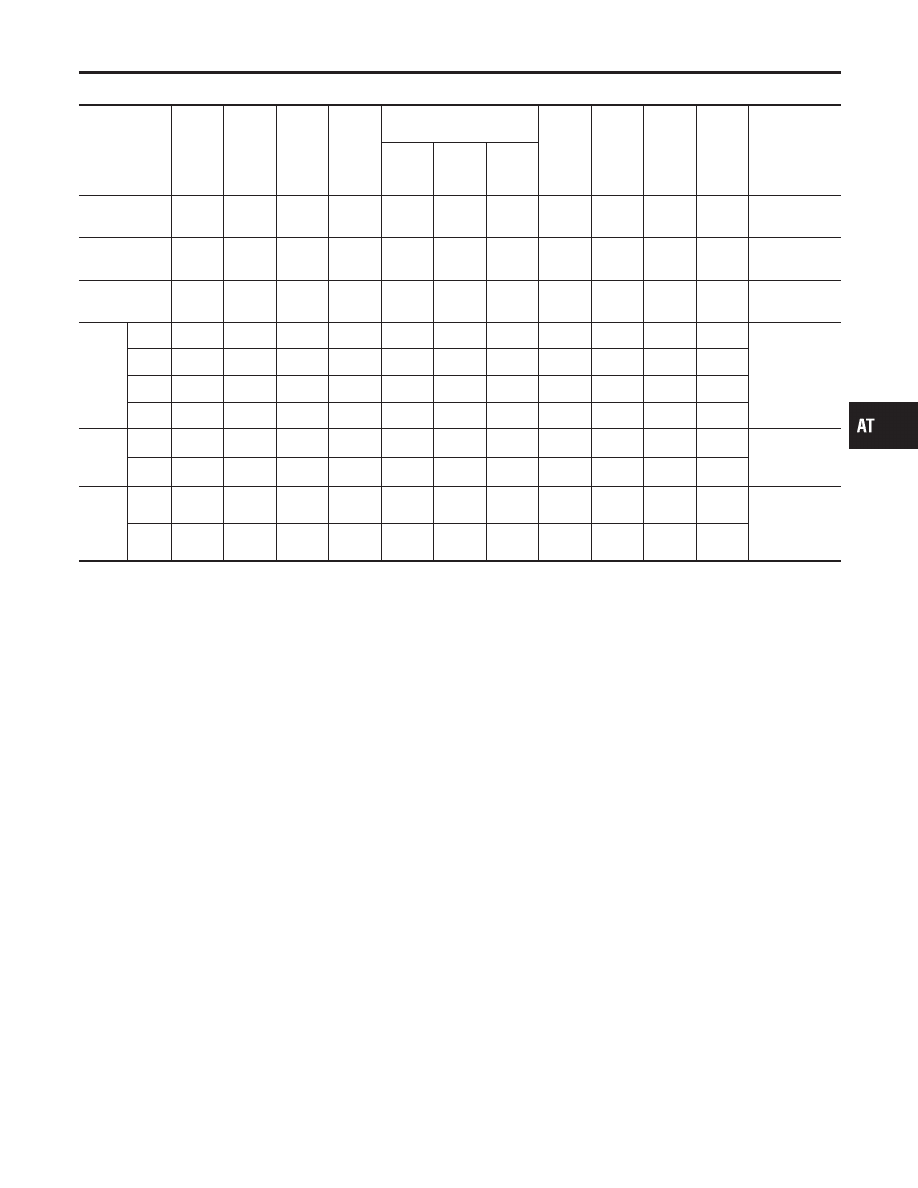
CLUTCH AND BAND CHART

NBAT0012S03

Shift position

Reverse

clutch

High

clutch

For-

ward

clutch

Over-

run

clutch

Band servo

For-

ward

one

-way

clutch

Low

one-

way

clutch

Low &

reverse

brake

Lock-up

Remarks

2nd

apply

3rd

release

4th

apply

P

PARK

POSITION

R

q

q

REVERSE
POSITION

N

NEUTRAL

POSITION

D*4

1st

q

*1D

B

B

Automatic

shift

1

k

2

k

3

k

4

2nd

q

*1A

q

B

3rd

q

q

*1A

*2C

C

B

*5

q

4th

q

C

*3C

C

q

q

2

1st

q

D

B

B

Automatic

shift

1

k

2

2nd

q

*1A

q

B

1

1st

q

q

B

q

Locks (held

stationary) in

1st speed

1

g

2

2nd

q

q

q

B

*1: Operates when overdrive control switch is being set in “OFF” position.
*2: Oil pressure is applied to both 2nd “apply” side and 3rd “release” side of band servo piston. However, brake band does not contract
because oil pressure area on the “release” side is greater than that on the “apply” side.
*3: Oil pressure is applied to 4th “apply” side in condition *2 above, and brake band contracts.
*4: A/T will not shift to 4th when overdrive control switch is set in “OFF” position.
*5: Operates when overdrive control switch is “OFF”.

q

: Operates.

A: Operates when throttle opening is less than 3/16, activating engine brake.
B: Operates during “progressive” acceleration.
C: Operates but does not affect power transmission.
D: Operates when throttle opening is less than 3/16, but does not affect engine brake.

GI

MA

EM

LC

EC

FE

TF

PD

AX

SU

BR

ST

RS

BT

HA

SC

EL

IDX

OVERALL SYSTEM

Shift Mechanism (Cont’d)

AT-17

POWER TRANSMISSION

=NBAT0012S04

“N” and “P” Positions

NBAT0012S0401

I

“N” position
No control members operate. Power from the input shaft is not transmitted to the output shaft since the
clutch does not operate.

I

“P” position
Similar to the “N” position, no control members operate. The parking pawl interconnected with the select
lever engages with the parking gear to mechanically hold the output shaft so that the power train is locked.

SAT039J

OVERALL SYSTEM

Shift Mechanism (Cont’d)

AT-18

“1

1

” Position

=NBAT0012S0406

Forward clutch
Forward one-way clutch
Overrun clutch
Low and reverse brake

As overrun clutch engages, rear internal gear is locked by the operation of low and
reverse brake.
This is different from that of D

1

and 2

1

.

Engine brake

Overrun clutch always engages, therefore engine brake can be obtained when decelerat-
ing.

SAT100J

GI

MA

EM

LC

EC

FE

TF

PD

AX

SU

BR

ST

RS

BT

HA

SC

EL

IDX

OVERALL SYSTEM

Shift Mechanism (Cont’d)

AT-19

“D

1

” and “2

1

” Positions

=NBAT0012S0402

Forward one-way clutch
Forward clutch
Low one-way clutch

Rear internal gear is locked to rotate counterclockwise because of the functioning of
these three clutches. (Start-up at D

1

)

Overrun clutch
engagement conditions
(Engine brake)

D

1

: Overdrive control switch in “OFF”

Throttle opening less than 3/16

2

1

: Throttle opening less than 3/16

At D

1

and 2

1

positions, engine brake is not activated due to free turning of low one-way

clutch.

SAT096J

OVERALL SYSTEM

Shift Mechanism (Cont’d)

AT-20


Content   ..  3  4  5  6   ..