Infiniti Q45. Manual - part 903
TROUBLE DIAGNOSIS
WT-21
C
D
F
G
H
I
J
K
L
M
A
B
WT
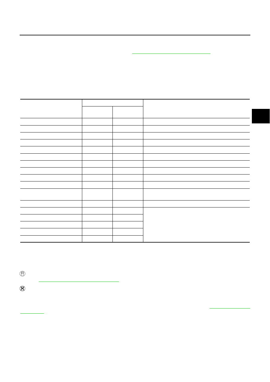
DATA MONITOR MODE
Operation Procedure
1.
Perform “CONSULT-II Start Procedure”. Refer to
GI-36, "CONSULT-II Start Procedure"
.
2.
Touch “DATA MONITOR”.
3.
Select from “SELECT MONITOR ITEM”, screen of data monitor mode is displayed.
NOTE:
When malfunction is detected, CONSULT-II performs REAL-TIME DIAGNOSIS.
Also, any malfunction detected while in this mode will be displayed in real time.
Display Item List
×
: Standard
–: Not applicable
LOW TIRE PRESSURE WARNING CONTROL UNIT PART NUMBER MODE
Ignore the low tire pressure warning control unit part number displayed in the “ECU PART NUMBER”.
Refer to parts catalog to order the low tire pressure warning control unit.
Self-Diagnostic Procedure
NES000D6
SELF-DIAGNOSTIC PROCEDURE (WITH CONSULT-II)
Refer to
WT-19, "SELF-DIAG RESULT MODE"
.
SELF-DIAGNOSTIC PROCEDURE (WITHOUT CONSULT-II)
Description
The low tire pressure warning lamp in the combination meter will flicker according to the self-diagnostic
results. As for the details of the low tire pressure warning lamp flickering patterns, refer to
Monitored item (Unit)
Monitor item selection
Remarks
MAIN
SIGNALS
SELECTION
FROM MENU
VHCL SPEED SE [km/h] or [mph]
×
×
Vehicle speed is displayed.
AIR PRESS FL [kpa] or [psi]
×
×
Senses the front LH tire pressure is displayed.
AIR PRESS FR [kPa] or [psi]
×
×
Senses the front RH tire pressure is displayed.
AIR PRESS RR [kpa] or [psi]
×
×
Senses the rear RH tire pressure is displayed.
AIR PRESS RL [kpa] or [psi]
×
×
Senses the rear LH tire pressure is displayed.
ID REGST FL [DONE/YET]
×
×
Registration status of front LH ID is displayed.
ID REGST FR [DONE/YET]
×
×
Registration status of front RH ID is displayed.
ID REGST RR [DONE/YET]
×
×
Registration status of rear RH ID is displayed.
ID REGST RL [DONE/YET]
×
×
Registration status of rear LH ID is displayed.
WARNING LAMP [ON/OFF]
×
×
Control status of low tire pressure warning lamp is displayed.
BUZZER [ON/OFF]
×
×
Control status of buzzer in low tire pressure warning lamp
control unit is displayed.
Voltage [V]
–
×
The value measured by the voltage probe is displayed.
Frequency [Hz]
–
×
The value measured by the pulse probe is displayed.
DUTY-HI (high) [%]
–
×
DUTY-LOW (low) [%]
–
×
PLS WIDTH-HI [msec]
–
×
PLS WIDTH-LOW [msec]
–
×