Infiniti Q45. Manual - part 900
LOW TIRE PRESSURE WARNING SYSTEM
WT-9
C
D
F
G
H
I
J
K
L
M
A
B
WT
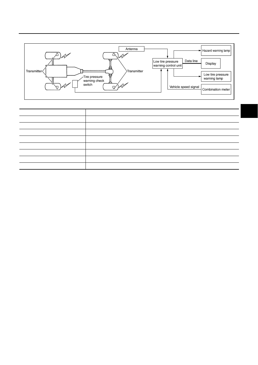
System Diagram
NES000CY
COMPONENTS FUNCTION DESCRIPTION
SEIA0741E
Component parts
Function
Low tire pressure warning control unit
Monitors tire pressure and controls the low tire pressure warning lamp and turn signal lamp.
Transmitter
Converts tire pressure signals to radio signals.
Antenna
Receives radio signals converted from tire pressure signals.
Display
Displays the air pressure of each tire.
Tire pressure warning check switch
Allows a mode to be switched to a diagnosis mode.
Hazard warning lamp
ID registration of each wheel has been completed, turn signal lamp flashes two times.
Combination meter
Transmitters the vehicle speed signal to low tire pressure warning control unit.
Low tire pressure warning lamp
Illuminates if malfunction is detected in electrical system of low tire pressure warning system.