Infiniti Q45. Manual - part 897
REAR ACTIVE STEER
STC-91
[WITH REAR ACTIVE STEER]
C
D
E
F
H
I
J
K
L
M
A
B
STC
REAR ACTIVE STEER
PFP:55705
Removal and Installation
NGS0004K
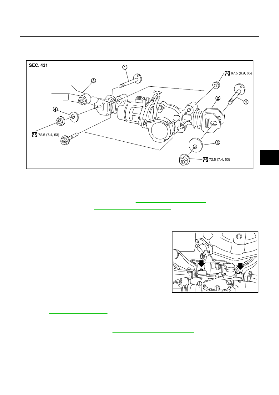
COMPONENTS
REMOVAL
1.
Remove center muffler with power tool. Refer to
EX-3, "Removal and Installation"
.
2.
Remove coil spring. Refer to
RSU-16, "Removal and Installation"
NOTE:
Put the adjustment position marks of wheel alignment on the adjusting bolts and decenter cam.
3.
Disconnect each harness connectors from RAS actuator assembly and rear suspension member.
4.
Remove fixing bolts and nuts of RAS actuator assembly (1), and
then remove RAS actuator assembly (1) from rear suspension
member.
INSTALLATION
Note the following, and installation is the reverse order of removal.
●
Refer to
●
When installing RAS actuator assembly to rear suspension member, check the mounting surfaces of RAS
actuator assembly and rear suspension member for oil, dirt, sand, or other foreign materials.
●
Adjust rear wheel alignment. Refer to
RSU-5, "Wheel Alignment Inspection"
.
1.
Adjust bolt
2.
RAS actuator assembly
3.
Rear lower link
4.
Decenter cam
Refer to
, for the symbols in the figure.
SGIA1505E
SGIA1506E