Infiniti Q45. Manual - part 895
TROUBLE DIAGNOSIS FOR SYSTEM
STC-83
[WITH REAR ACTIVE STEER]
C
D
E
F
H
I
J
K
L
M
A
B
STC
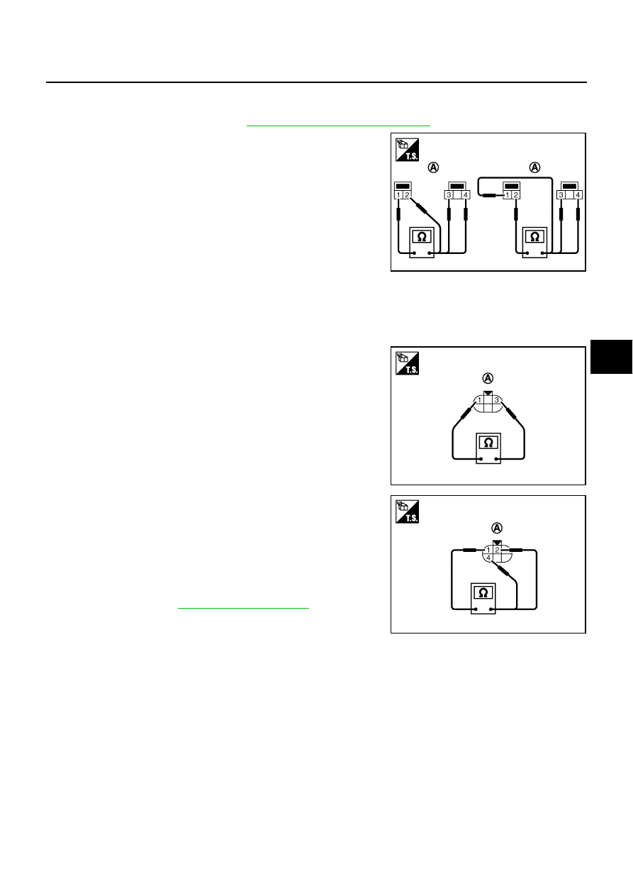
NOISE SUPPRESSOR
1.
Turn ignition switch “OFF”.
2.
Remove noise suppressor. Refer to
STC-41, "Component Parts Location"
3.
Check noise suppressor connector (A) continuity between the
following terminals.
4.
If NG, replace the noise suppressor.
REAR WHEEL STEERING ANGLE SENSOR
1.
Turn ignition switch “OFF”.
2.
Disconnect rear wheel steering angle sensor harness connector.
3.
Remove rear wheel steering angle sensor.
4.
Check resistance between rear wheel steering angle sensor
connector (A) B81 terminals 1 and 3.
5.
While turning the rear wheel steering angle sensor clockwise or
counterclockwise, check rear wheel steering angle sensor con-
nector (A) B81 terminals 1 and 2, 4.
6.
When replacing rear wheel steering angle sensor, perform the
neutral position adjustment after replacing rear wheel steering
angle sensor. Refer to
.
1 – 3
: Continuity should exist.
1 – 2
: Continuity should no exist.
1 – 4
: Continuity should no exist.
2 – 1
: Continuity should no exist.
2 – 3
: Continuity should no exist.
2 – 4
: Continuity should exist.
SGIA1467E
1 - 3
: 1 k
Ω
SGIA1485E
1 - 2
: 1.2 k – 1.5 k
Ω
1 - 4
: 1.2 k – 1.5 k
Ω
SGIA1486E