Infiniti Q45. Manual - part 827
AUTOMATIC DRIVE POSITIONER
SE-63
C
D
E
F
G
H
J
K
L
M
A
B
SE
Check Sliding Sensor Circuit
NIS0012W
1.
CHECK SLIDING SENSOR MECHANISM
Check the operation malfunction caused by sliding rail deformation or parts are loose.
OK or NG
OK
>> GO TO 2.
NG
>> Repair the malfunctioning part and check again.
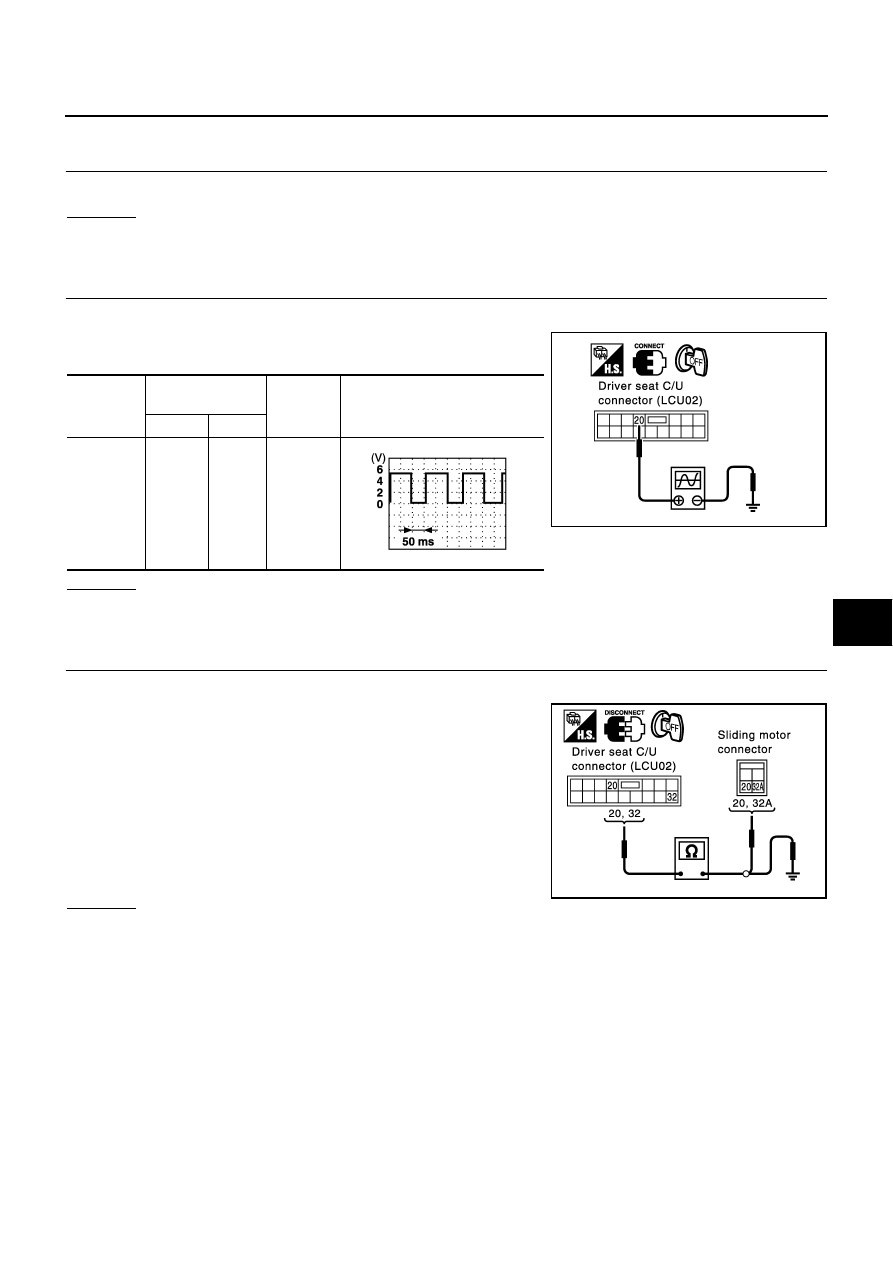
2.
CHECK SLIDING SENSOR INPUT/OUTPUT SIGNAL
1.
Turn ignition switch OFF.
2.
Check signal between driver seat control unit connector and
ground, with oscilloscope.
OK or NG
OK
>> System is OK.
NG
>> GO TO 3.
3.
CHECK HARNESS CONTINUITY
1.
Disconnect driver seat control unit connector and sliding motor connector.
2.
Check continuity between driver seat control unit connector
B143 terminals 20, 32 and sliding motor B146 terminals 20, 32A.
3.
Check continuity between driver seat control unit B143 terminals
20, 32 and ground.
OK or NG
OK
>> Replace sliding motor.
NG
>> Repair or replace harness between driver seat control unit and sliding motor.
Connector
Terminals
(Wire color)
Condition
Signal
(Reference valve)
(+)
(–)
B143
20 (G/B)
Ground
Sliding
motor
operation
PIIA4130E
PIIA3277E
20 (G/B) – 20 (G/B)
: Continuity should exist.
32 (R/W) – 32A (R/W)
: Continuity should exist.
20 (G/B) – Ground
:Continuity should not exist.
32 (R/W) – Ground
:Continuity should not exist.
PIIA4129E