Infiniti Q45. Manual - part 807
TROUBLE DIAGNOSIS FOR SYSTEM
SCS-45
C
D
F
G
H
I
J
K
L
M
A
B
SCS
6.
CHECK HARNESS BETWEEN ACTIVE DAMPER SUSPENSION CONTROL UNIT AND REAR SHOCK
ABSORBER ACTUATOR LH
1.
Turn ignition switch “OFF”.
2.
Disconnect active damper suspension control unit harness connector and the rear shock absorber actua-
tor LH harness connector.
3.
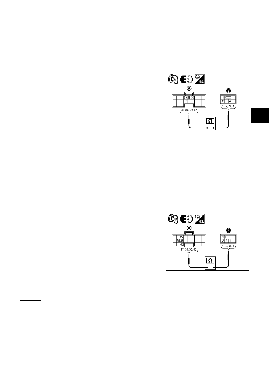
Check continuity between the following terminals.
–
Active damper suspension control unit harness connector (A)
B38 terminal 28 and rear shock absorber actuator LH harness
connector (B) B26 terminal 2.
–
Active damper suspension control unit harness connector (A)
B38 terminal 29 and rear shock absorber actuator LH harness
connector (B) B26 terminal 3.
–
Active damper suspension control unit harness connector (A)
B38 terminal 30 and rear shock absorber actuator LH harness
connector (B) B26 terminal 4.
–
Active damper suspension control unit harness connector (A)
B38 terminal 37 and rear shock absorber actuator LH harness connector (B) B26 terminal 1.
Also check harness for short to ground and short to power.
OK or NG
OK
>> GO TO 7.
NG
>> Repair or replace damaged parts.
7.
CHECK HARNESS BETWEEN ACTIVE DAMPER SUSPENSION CONTROL UNIT AND REAR SHOCK
ABSORBER ACTUATOR RH
1.
Turn ignition switch “OFF”.
2.
Disconnect active damper suspension control unit harness connector and the rear shock absorber actua-
tor RH harness connector.
3.
Check continuity between the following terminals.
–
Active damper suspension control unit harness connector (A)
B38 terminal 27 and rear shock absorber actuator RH harness
connector (B) B226 terminal 3.
–
Active damper suspension control unit harness connector (A)
B38 terminal 35 and rear shock absorber actuator RH harness
connector (B) B226 terminal 1.
–
Active damper suspension control unit harness connector (A)
B38 terminal 36 and rear shock absorber actuator RH harness
connector (B) B226 terminal 4.
–
Active damper suspension control unit harness connector (A)
B38 terminal 45 and rear shock absorber actuator RH harness connector (B) B226 terminal 2.
Also check harness for short to ground and short to power.
OK or NG
OK
>> GO TO 8 (with CONSULT-II).
>> GO TO 9 (without CONSULT-II).
NG
>> Repair or replace damaged parts.
Continuity should exist.
SEIA0720E
Continuity should exist.
SEIA0721E