Infiniti Q45. Manual - part 797
ACTIVE DAMPER SUSPENSION SYSTEM
SCS-5
C
D
F
G
H
I
J
K
L
M
A
B
SCS
ACTIVE DAMPER SUSPENSION
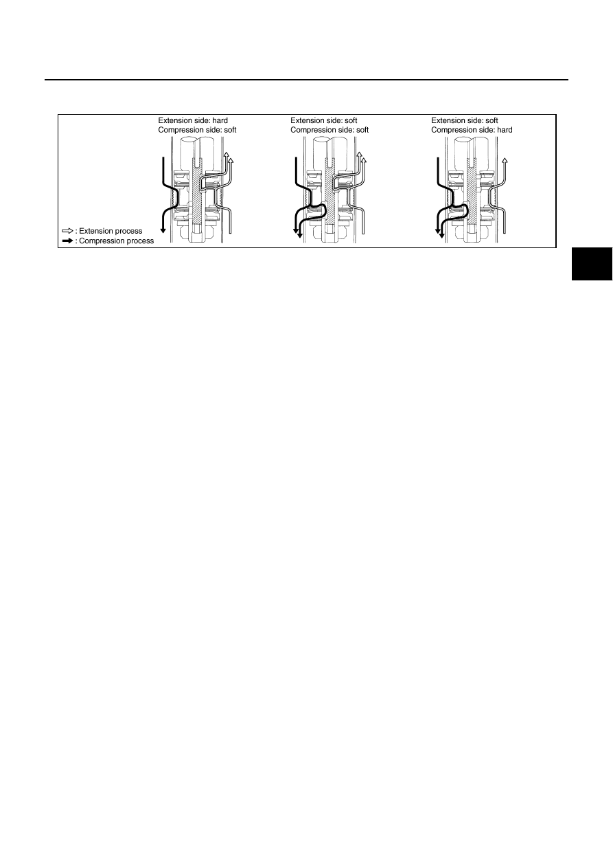
Operation Principle
Extension side: hard
●
The oil groove of spool is closed.
●
The oil flowed from the extension side oil flow inlet via the extension side main valve. The oil flow amount
is minimized, and the damping force of shock absorber rises.
Compression side: hard
●
The oil groove of spool is closed.
●
The oil flowed from the compression side oil flow inlet via the compression side main valve. The oil flow
amount is minimized, and the damping force of shock absorber rises.
Extension side: soft
●
The oil grooves of spool and stud are open.
●
The oil flowed through 2 passages (one passage is from the extension side oil flow inlet via the extension
side main valve and another passes the oil groove of spool via the extension side check valve). Therefore,
the oil flow amount is maximized, and the damping force of shock absorber will weaken.
Compression side: soft
●
The oil grooves of spool and stud are open
●
The oil flowed through 2 passages (one passage is from the compression side oil flow inlet via the com-
pression side main valve and another passes the oil groove of spool via the compression side check
valve). Therefore, the oil flow amount is maximized, and the damping force of shock absorber will weaken.
VERTICAL G SENSOR
It detects the upper/lower acceleration applied to the vehicle body (front/rear).
STEERING ANGLE SENSOR
It detects the steering wheel angle.
SHOCK ABSORBER ACTUATOR
It rotates the spool, opens/closes the oil passage of stud (changes the flow amount), and then controls the
damping force of shock absorber.
SHOCK ABSORBER
It continuously switches the damping force at the wide range in a short time and can control the damping
forces of extension side and compression side individually.
ACTIVE DAMPER SUSPENSION SELECT SWITCH
AUTO (normal driving) mode and SPORT (sports driving) mode can be changed. When selecting the SPORT
mode, SPORT indicator in combination meter illuminates.
SPORT INDICATOR LAMP
●
SPORT indicator lamp in combination meter is illuminated (SPORT mode) or turned off (AUTO mode) by
switching the active damper suspension select switch, and it indicates the modes.
●
It indicates a system malfunction (when the fail-safe function is activated) and the self-diagnostic results
by turning on or blinking.
SEIA0701E