Infiniti Q45. Manual - part 779
FRONT LOWER LINK
RSU-15
C
D
F
G
H
I
J
K
L
M
A
B
RSU
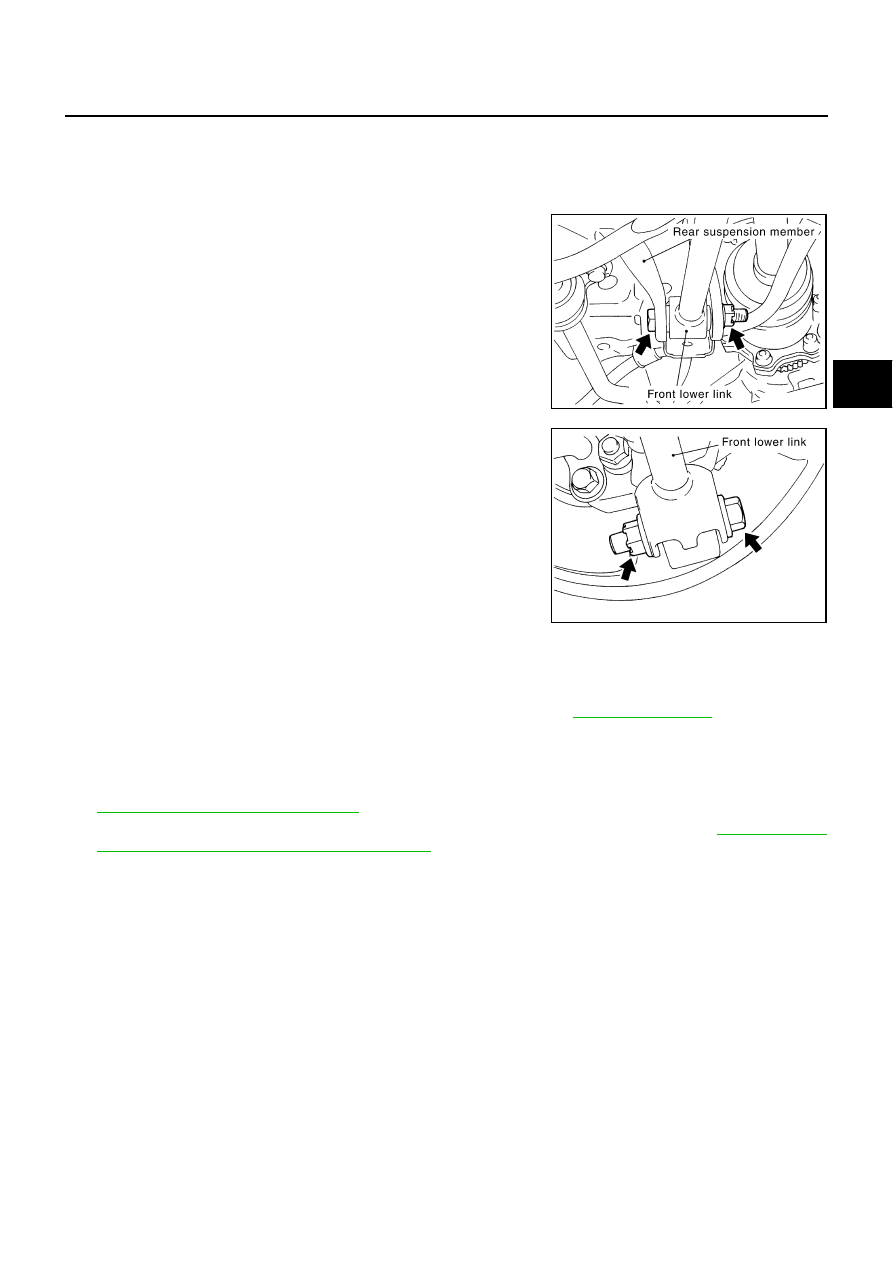
FRONT LOWER LINK
PFP:55110
Removal and Installation
NES000HQ
REMOVAL
1.
Remove tires from vehicle with power tool.
2.
Remove mounting nut and bolt between front lower link and rear
suspension member with power tool.
3.
Remove fixing bolt and nut in axle housing side of front lower
link with power tool.
4.
Remove front lower link from vehicle.
INSPECTION AFTER REMOVAL
Check front lower link and bushing for deformation, cracks, and other damage. Replace if necessary.
INSTALLATION
●
Install in the reverse order of removal. For tightening torque, refer to
.
NOTE:
Do not reuse non-reusable parts.
●
Perform final tightening of nuts and bolts of rear suspension member and axle housing installation position
(rubber bushing) under unladen conditions with tires on level ground. Check wheel alignment. Refer to
RSU-5, "Wheel Alignment Inspection"
●
Adjust neutral position of steering angle sensor after wheel alignment inspection. Refer to
ment of Steering Angle Sensor Neutral Position"
SEIA0457E
SDIA2278E