Infiniti Q45. Manual - part 758
REAR DRIVE SHAFT
RAX-13
C
E
F
G
H
I
J
K
L
M
A
B
RAX
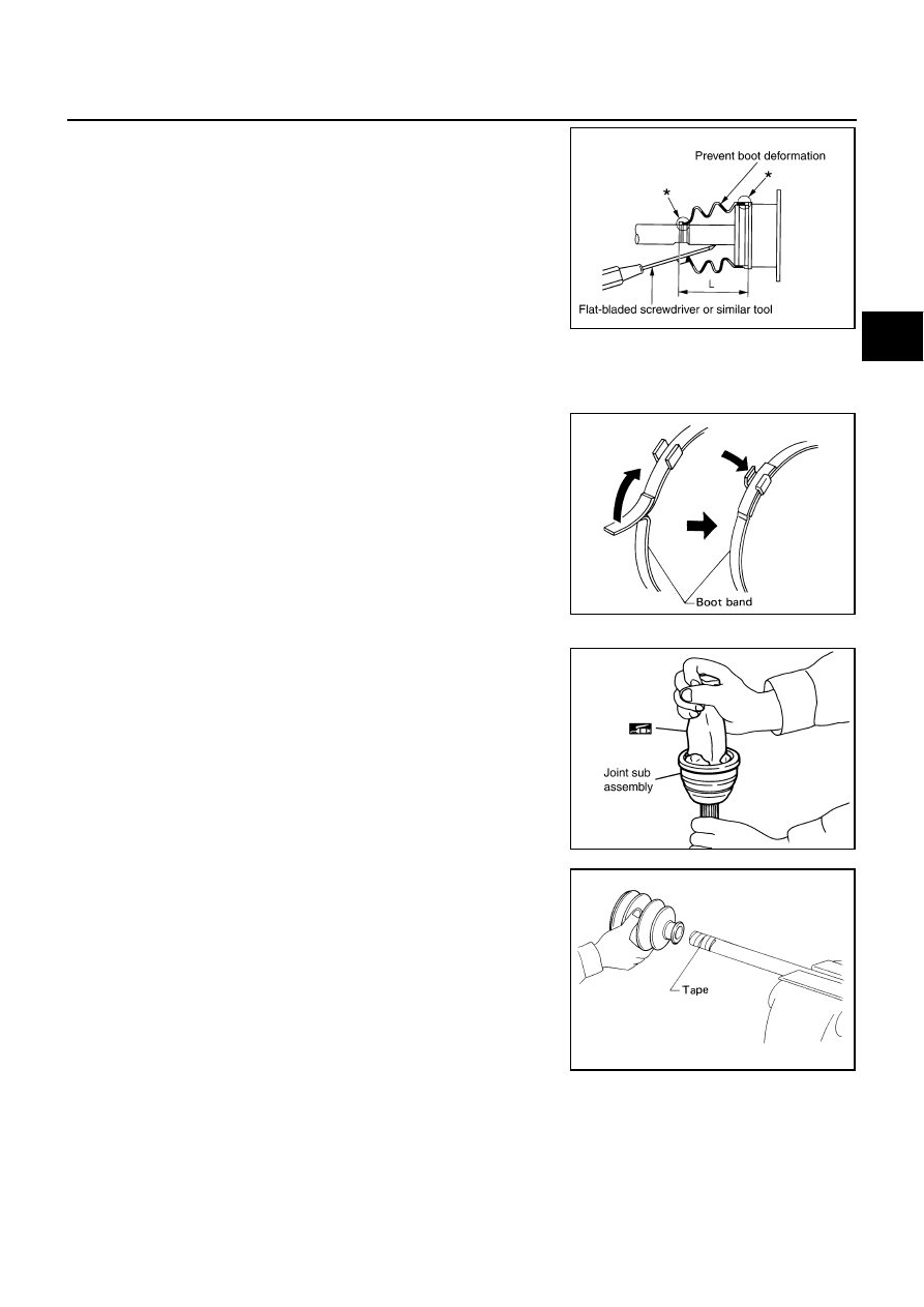
8.
Position boot securely into grooves (indicated by * marks)
shown in the figure.
CAUTION:
If there is grease on boot mounting surfaces (indicated by*
marks) of shaft and housing, boot may come off. Remove
all grease from surfaces.
9.
Make sure the boot installation length “L” is the length indicated
below. Insert a flat-bladed screwdriver or similar tool into the
smaller side of boot. Bleed air from boot to prevent boot defor-
mation.
CAUTION:
●
Boot may break if boot installation length is out of the standard value.
●
Take care not to touch the tip of screwdriver to inside of boot.
10. Secure the big and small ends of boot with new boot bands as
shown in the figure.
NOTE:
Discard old boot bands; replace with new ones.
11. After installing housing and shaft, rotate boot to check whether
or not the actual position is correct. If boot position is not correct,
secure boot with new boot band again.
Wheel Side
1.
Insert the majority of the specified amount grease (NISSAN gen-
uine grease or equivalent) into joint sub-assembly serration hole
until grease begins to ooze from ball groove and serration hole.
After insert grease, use a shop cloth to wipe off old grease that
has oozed out.
2.
Wind serrated part of shaft with tape. Install boot band and boot
to shaft. Be careful not to damage boot.
NOTE:
Discard old boot band and boot; replace with new ones.
3.
Remove protective tape wound around serrated part of shaft.
Boot installation Length “L”
: 93.9 mm (3.697 in)
SDIA2400E
SFA395
SDIA1127E
SFA800