Infiniti Q45. Manual - part 753


  Index      Infiniti     Infiniti Q45 - service repair manual 2006 year


Search            copyright infringement  


Content   ..  751  752  753  754   ..


Infiniti Q45. Manual - part 753


POWER STEERING OIL PUMP

PS-29

C

D

E

F

H

I

J

K

L

M

A

B

PS

DISASSEMBLY

NOTE:
Secure oil pump in a vise if necessary.

CAUTION:

When retaining the drive shaft in a vise, always use the copper or aluminum plates between vise and
shaft.

1.

Remove rear cover mounting bolts and then remove rear cover from body assembly.

2.

Remove gasket from body assembly.

3.

Remove dowel pin, cartridge and side plate from body assembly.

4.

Remove pulley mounting nut and then remove pulley from drive shaft.

5.

Remove bracket mounting bolts and then remove bracket from body assembly.

6.

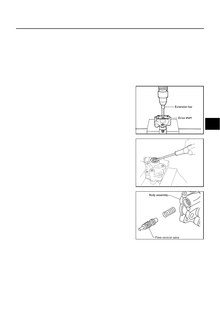
Remove snap ring from drive shaft assembly and press out it.

CAUTION:

When removing the snap ring, be careful not to damage the
drive shaft assembly.

7.

Remove oil seal from body assembly using a flat-bladed screw-
driver.

CAUTION:

Never damage the body assembly.

8.

Remove O-ring from body assembly.

9.

Loosen lock nut and remove washer, O-ring, joint then remove
connector bolt, O-ring and pull out flow control valve and spring
from body assembly.

CAUTION:

Be careful not to drop and deform the flow control valve. 

10. Remove suction pipe from body assembly.

11. Remove O-ring for suction pipe.

INSPECTION AFTER DISASSEMBLY
Body Assembly and Rear Cover Inspection

Check body assembly and the inside of rear cover for damage. If any damage is found, replace with new part
for rear cover, and replace with new power steering pump assembly for body assembly.

Cartridge Assembly Inspection

Check cam ring, side plate, rotor and vane for damage. If any damage is found, replace cartridge assembly
with new one.

Side Plate Inspection

Check side plate for damage. Replace side plate if there are.

SST010B

SST034A

SGIA0524E

PS-30

POWER STEERING OIL PUMP

Flow Control Valve Inspection

Check flow control valve and spring for damage. Replace if there are.

ASSEMBLY

NOTE:
Secure oil pump in a vise if necessary.

CAUTION:

Use copper plates when securing in a vise.

1.

Apply multi purpose grease to oil seal lips (1). Apply Genuine
Nissan PSF or equivalent to around oil seal, and then install oil
seal to body assembly.

CAUTION:

Never reuse the oil seal

2.

Apply Genuine Nissan PSF or equivalent to drive shaft, and
press drive shaft into body assembly, then install snap ring.

CAUTION:

Never reuse the snap ring.

3.

Apply Genuine Nissan PSF or equivalent to O-ring, and install
O-ring into body assembly.

CAUTION:

Never reuse the O-ring.

4.

Install side plate to body assembly.

5.

Install dowel pin (1) into dowel pin hole (

), and install cam ring

(2) pointing it's D1 side toward the body assembly (3) side as
shown in the figure.

CAUTION:

When installing the cam-ring, turn carved face with a let-
ter “E” of it to the rear cover.

Never confuse the assembling direction of the cam ring.
If cam ring is installed facing the incorrect direction, it
may cause pump operation malfunction.

SGIA1150E

SGIA0422E

SGIA1599E

POWER STEERING OIL PUMP

PS-31

C

D

E

F

H

I

J

K

L

M

A

B

PS

6.

Install rotor to body assembly.

CAUTION:

When installing the rotor, turn punch mark face on rotor to
body assembly.

7.

Install vane to rotor with facing the round portion outside.

8.

Check if drive shaft assembly turns smoothly.

9.

Install gasket to body assembly.

CAUTION:

Never reuse the gasket.

10. Install rear cover to body assembly and tighten bolts at the spec-

ified torque. Refer to 

PS-28, "COMPONENT"

 .

11. Install pulley to drive shaft assembly then tighten lock nut at the

specified torque. Refer to 

PS-28, "COMPONENT"

 .

12. Install spring, flow control valve, O-ring, connector bolt, joint,

washer to body assembly. Then tighten lock nut at the specified
torque. Refer to 

PS-28, "COMPONENT"

 .

CAUTION:

Never reuse the O-ring.

13. Apply Genuine Nissan PSF or equivalent to O-ring and install O-

ring to body assembly.

CAUTION:

Never reuse the O-ring.

14. Install suction pipe to body assembly.

SGIA0424E

SST843A

SGIA0425E

PS-32

HYDRAULIC LINE

HYDRAULIC LINE

PFP:49721

Removal and Installation

NGS00031

Refer to the figure for hydraulic line removal and installation information.

CAUTION:

Securely insert harness connector to pressure sensor.

Never reuse the O-ring.

Apply Genuine Nissan PSF or equivalent to around the O-
ring (1), then install the drain port (2) and high pressure
pipe (3) to the gear sup-assembly (4).

1.

Low pressure hose

2.

High pressure pipe

3.

Steering gear assembly

4.

Clip

5.

Low pressure pipe

6.

High pressure piping

7.

Pressure sensor

8.

Reservoir tank

9.

Suction hose

10. Oil pump assembly

11.

High pressure hose

Refer to 

GI-9, "Components"

 , for the symbols in the figure.

Specified torque

Drain port

: 33.4 N·m (3.4kg-m, 25ft-lb)

High pressure pipe

: 19.5 N·m (2.0kg-m, 14ft-lb)

SGIA1372E

SGIA1559E


Content   ..  751  752  753  754   ..