Infiniti Q45. Manual - part 748
STEERING WHEEL
PS-9
C
D
E
F
H
I
J
K
L
M
A
B
PS
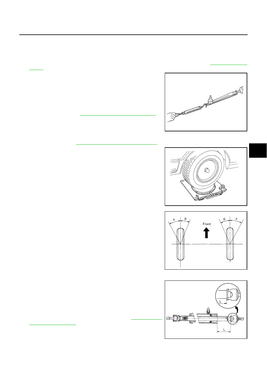
RACK SLIDING FORCE
1.
Start engine.
2.
Bring power steering fluid up to adequate operating temperature. [Make sure temperature of fluid is
approximately 50 to 80
°
C (122 to 176
°
F).]
3.
Disconnect lower joint and steering knuckle from steering gear assembly. Refer to
4.
While pulling outer socket slowly in
±
11.5 mm (
±
0.453 in) range
from neutral position, make sure rack sliding force is within
specification.
5.
If rack sliding force is not within specification, overhaul steering
gear assembly. Refer to
PS-17, "Disassembly and Assembly"
.
FRONT WHEEL TURNING ANGLE
1.
FSU-17, "Wheel Alignment (Unladen*)"
2.
Place front wheels on turning radius gauges and rear wheels on
stands so that vehicle can be level. Check the maximum inner
and outer wheel turning angles for LH and RH road wheels.
3.
Start engine and run at idle, turn steering wheel all the way right
and left, measure the turning angle.
4.
Check the following items when turning angle is out of the standard.
a.
Check rack stroke.
b.
Disassemble steering gear assembly to check the cause that
rack stroke is outside of the standard. Refer to
.
c.
Steering angles are not adjustable. Check steering gear assem-
bly, steering column assembly and front suspension compo-
nents for wear or damage if any of the turning angles are
different from the specified value. Replace any of them, if any non-standard condition exists.
Rack sliding force:
255 - 294 N (26.1 - 29.9 kg, 57.4 - 66.0 lb)
SST090B
SMA127
Inner wheel (Angle: A)
Minimum
: 39
°
45
′
(39.75
°
)
Nominal
: 42
°
45
′
(42.75
°
)
Maximum
: 43
°
45
′
(43.75
°
)
Outer wheel (Angle: B)
Nominal
: 33
°
50
′
(33.83
°
)
SGIA0055E
Rack stroke “L”
Except for RAS models
: 68.5 mm (2.697 in)
RAS models
: 66.0 mm (2.598 in)
SGIA0629J