Index Infiniti Infiniti Q45 - service repair manual 2006 year
Search copyright infringement
Content .. 676 677 678 679 ..
Infiniti Q45. Manual - part 678
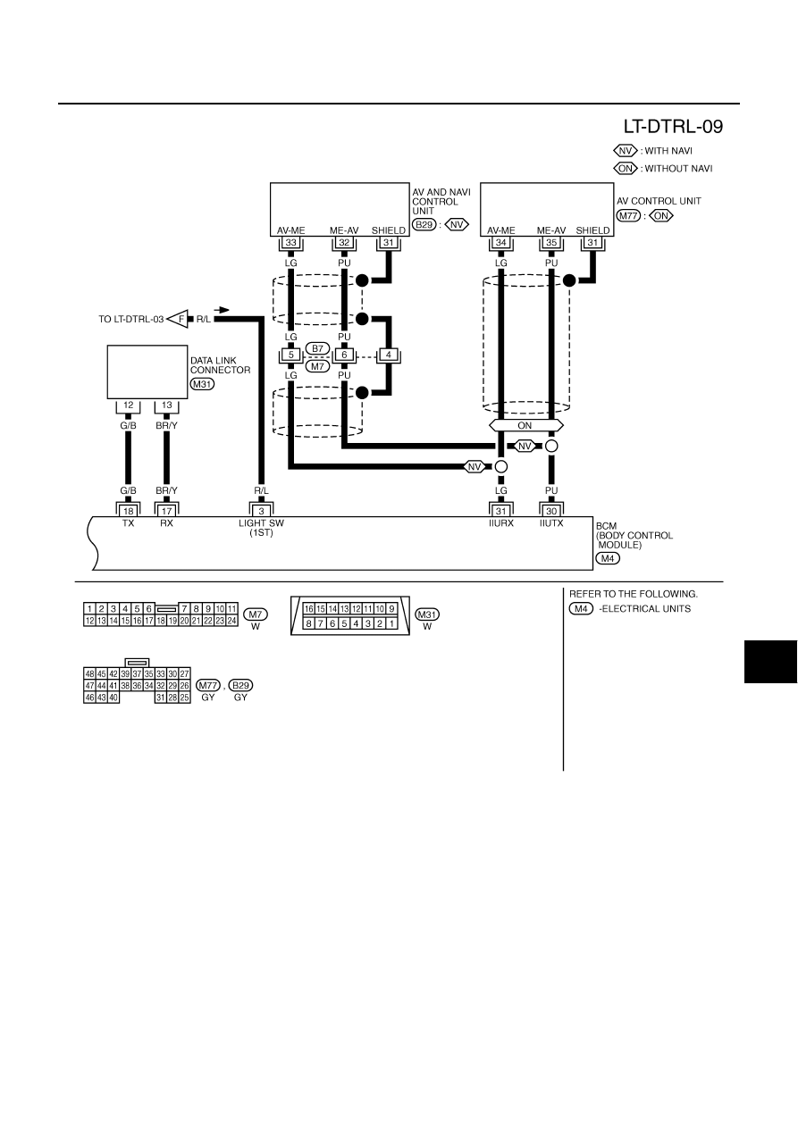
HEADLAMP (FOR CANADA) - DAYTIME LIGHT SYSTEM -
LT-49
C
D
E
F
G
H
I
J
L
M
A
B
LT
TKWM3693E