Infiniti Q45. Manual - part 667


  Index      Infiniti     Infiniti Q45 - service repair manual 2006 year


Search            copyright infringement  


Content   ..  665  666  667  668   ..


Infiniti Q45. Manual - part 667


HEADLAMP (FOR USA)

LT-5

C

D

E

F

G

H

I

J

L

M

A

B

LT

HEADLAMP (FOR USA)

PFP:26010

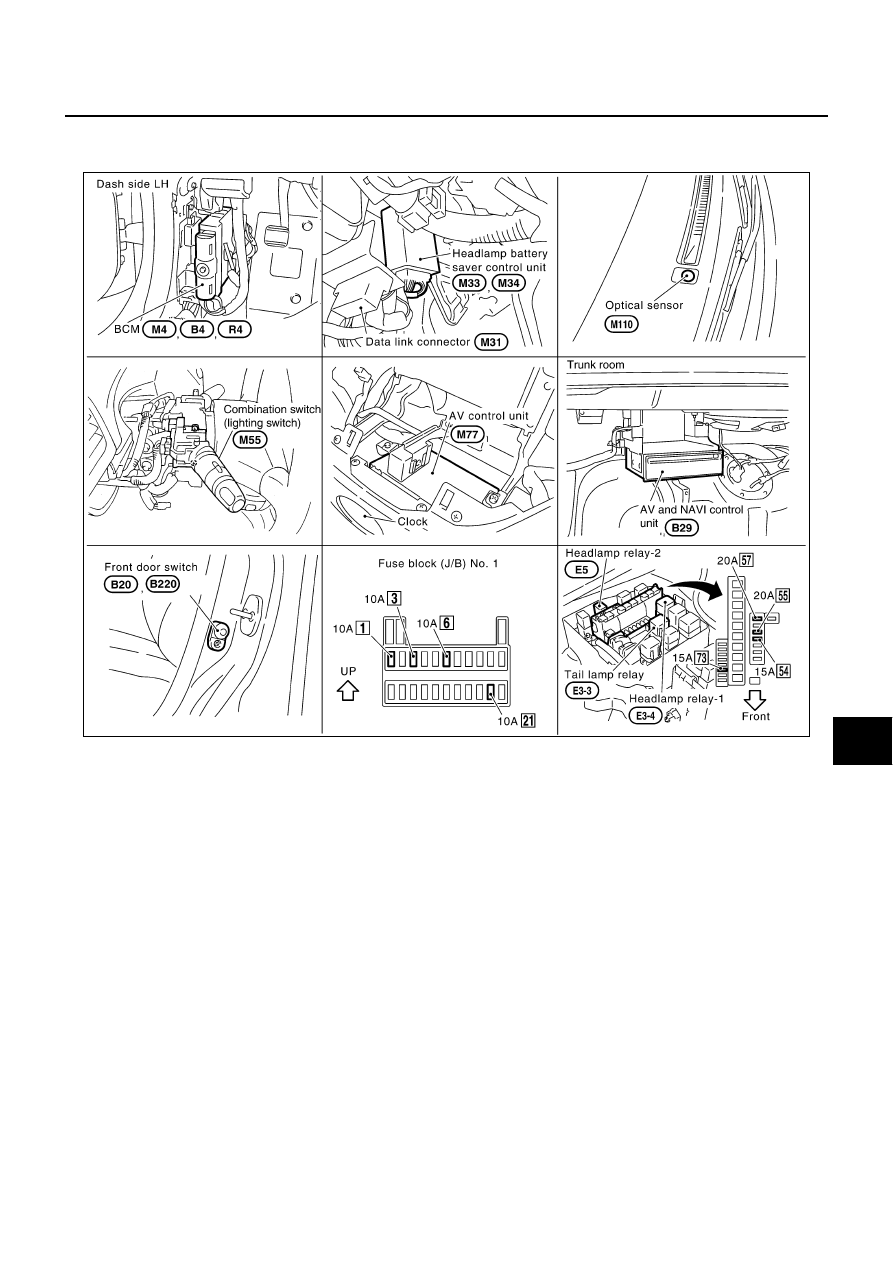
Component Parts and Harness Connector Location

NKS00174

System Description

NKS00175

The headlamp operation is controlled by the combination switch (lighting switch), which is connected to the
spiral cable and headlamp battery saver control unit. And the headlamp battery saver system is controlled by
the headlamp battery saver control unit and BCM (body control module).

OUTLINE

Power is supplied at all times

headlamp relay-1 terminal 2 from battery,

to BCM terminal 105

through 10A fuse [No. 3, located in fuse block (J/B) No. 1],

to headlamp relay-1 terminal 3

through 20A fuse [No. 57, located in fuse, fusible link and relay block (J/B)],

to headlamp relay-1 terminal 7

through 20A fuse [No. 55, located in fuse, fusible link and relay block (J/B)],

to headlamp relay-2 terminals 2 and 5

through 15A fuse [No. 73, located in fuse, fusible link and relay box],

to headlamp battery saver control unit terminal 7

through 10A fuse [No. 6, located in fuse block (J/B) No. 1],

to tail lamp relay terminals 2 and 6

through 15A fuse [No. 54, located in fuse, fusible link and relay block (J/B)].

When the ignition switch is in ON or START position, power is supplied

PKIB0994E

LT-6

HEADLAMP (FOR USA)

to headlamp battery saver control unit terminal 1, and

to BCM terminal 68

through 10A fuse [No. 1, located in fuse block (J/B) No. 1].

When the ignition switch is in ACC or ON position, power is supplied

to BCM terminal 60

through 10A fuse [No. 21, located in fuse block (J/B) No. 1].

Ground is supplied

to BCM terminals 56 and 113

through grounds M24 and M114,

to headlamp battery saver control unit terminals 4 and 11

through grounds M25 and M115.

Power Supply to Low Beam and High Beam

When lighting switch is in 2ND or PASS position, ground is supplied

to headlamp relay-1 and 2 terminals 1 from headlamp battery saver control unit terminals 2 and 8

through headlamp battery saver control unit terminals 3 and 9,

through lighting switch terminals 12 and 8,

through grounds M25 and M115.

Headlamp relays are energized and then power is supplied to headlamps.

Low Beam Operation

When lighting switch is turned to 2ND position and moved to (LOW position), power is supplied

from headlamp relay-1 terminals 5 and 6

to each front combination lamp terminal 7.

Ground is supplied

to each front combination lamp terminal 8

through grounds E24, E42 and E62.

With power and ground supplied, low beam headlamps illuminate.

High Beam Operation/Flash-to-pass Operation

When lighting switch is turned to 2ND position and moved to (HIGH position or PASS position), power is sup-
plied

from headlamp relay-2 terminal 3

to each front combination lamp terminal 13, and

to combination meter terminal 48 for HIGH BEAM indicator.

Ground is supplied

to front combination lamp LH terminal 14

to combination meter terminal 47 for HIGH BEAM indicator

through lighting switch terminals 9 and 8

through grounds M25 and M115, and

to front combination lamp RH terminal 14

through lighting switch terminals 6 and 5

through grounds M25 and M115.

With power and ground supplied, the high beams headlamps and the HIGH BEAM indicator illuminate.

NOTE:
Headlamps will be forced to turn off when the driver door is opened with the ignition switch in OFF or
ACC position (when except for lighting switch is in “AUTO” position)
.

BATTERY SAVER CONTROL

When the ignition switch is turned from ON (or START) to OFF (or ACC) positions while headlamps are illumi-
nated, the RAP signal is supplied to terminal 10 of the headlamp battery saver control unit from BCM terminal
135.

HEADLAMP (FOR USA)

LT-7

C

D

E

F

G

H

I

J

L

M

A

B

LT

After counting 45 seconds by the RAP signal from the BCM to headlamp battery saver control unit, the ground
supply to terminal 1 of the headlamp relay-1 and -2 from headlamp battery saver control unit terminals 2 and 8
is terminated.
Then the headlamps are turned off.
The headlamps are turned off when driver or passenger door is opened even if 45 seconds have not passed
after the ignition switch is turned from ON (or START) to OFF (or ACC) positions while headlamps are illumi-
nated.
When the lighting switch is turned from OFF to 2ND after headlamps are turned to off by the battery saver con-
trol, ground is supplied

to headlamp battery saver control unit terminals 5 and 13 from lighting switch terminal 11, and then,

to headlamp relay-1 and -2 terminals 1 from headlamp battery saver control unit terminals 2 and 8

through headlamp battery saver control unit terminals 3 and 9, and

through lighting switch terminal 12.

Then headlamps illuminate again.

AUTO LIGHT OPERATION

The auto light control system has an optical sensor inside it that detects outside brightness.
When the lighting switch is in AUTO position, it automatically turns on/off the parking lamps and the head-
lamps in accordance with the outside brightness. Sensitivity can be adjusted in four steps. For details of set-
ting, refer to 

LT-17, "SETTING CHANGE FUNCTION FOR AUTO LIGHT SYSTEM"

 .

When lighting switch is in “AUTO” position, ground is supplied

to BCM terminal 14 

from lighting switch terminal 42.

When ignition switch is turn to “ON” or “START” position and
Outside brightness is darker than predetermined level, ground is supplied

to headlamp relay-1 and 2 terminals 1

through headlamp battery saver control unit terminal 2, 8 and 4, 11, and

to tail lamp relay terminal 1 

through headlamp battery saver control unit terminals 6, 14 and 4, 11.

Then headlamp relay-1, 2 and tail lamp relay are energized, headlamps (low or high) and tail lamps are illumi-
nated according to switch position.

Shut Off Delay

While the headlamps are lit in the auto-light operation mode, the ignition switch is turned from “ON” to “OFF”
position. The BCM no longer receives a voltage signal at terminal 68. This starts the auto light shut off delay
timer. The timer is set based on the resistance value at BCM terminal 6. With the timer running, the headlamps
remain lit. When the timer reaches the end of its cycle, the headlamps turn off. Headlamp lighting time can be
adjusted from about 0 to 3 minutes. (This function is not applicable to the tail lamps.)
Auto light shut off delay timer can be adjusted in seven steps. For the details of the setting, refer to 

LT-17,

"SETTING CHANGE FUNCTION FOR AUTO LIGHT SYSTEM"

 .

VEHICLE SECURITY SYSTEM

The vehicle security system will cause the high beams to flash if the system is triggered. Refer to 

BL-155,

"VEHICLE SECURITY (THEFT WARNING) SYSTEM"

 .

XENON HEADLAMP

Xenon type lamps are used for to the low beam headlamps. Xenon bulbs do not use a filament. Instead, they
produce light when a high voltage current is passed between two tungsten electrodes through a mixture of
xenon (an inert gas) and certain other metal halides. In addition to strong lighting power, electronic control of
the power supply gives the headlamps stable quality and tone color.
Followings are some advantages of the xenon type headlamp.

The light produced by the headlamps is white color similar to sunlight that is easy to the eyes.

Light output is nearly double that of halogen headlamps, affording increased area of illumination.

Retroreflected luminance increases and the contrast enhances on the wet road in the rain. That makes
visibility go up more than the increase of the light volume.

Power consumption is approximately 25 percent less than halogen headlamps, reducing battery load.

LT-8

HEADLAMP (FOR USA)

Schematic

NKS00176

TKWM0332E


Content   ..  665  666  667  668   ..