Infiniti Q45. Manual - part 629


  Index      Infiniti     Infiniti Q45 - service repair manual 2006 year


Search            copyright infringement  


Content   ..  627  628  629  630   ..


Infiniti Q45. Manual - part 629


REVERSE INTERLOCK DOOR MIRROR SYSTEM

GW-109

C

D

E

F

G

H

J

K

L

M

A

B

GW

2. 

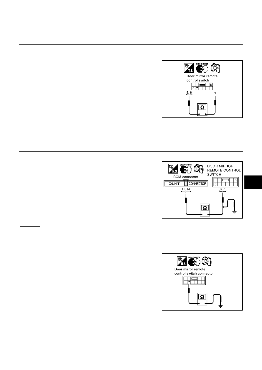
DOOR MIRROR REMOTE CONTROL SWITCH (CHANGEOVER SWITCH) INSPECTION

1.

Turn ignition switch OFF.

2.

Disconnect door mirror remote control switch connector.

3.

Check continuity between door mirror remote control switch ter-
minal 5 (RH), 6 (LH) and 7.

OK or NG

OK

>> GO TO 3.

NG

>> Replace the door mirror remote control switch.

3. 

HARNESS CONTINUITY INSPECTION

1.

Disconnect BCM connector.

2.

Check continuity between BCM connector M4 terminals 21, 24
and door mirror remote control switch connector M19 terminals
5, 6.

3.

Check continuity between BCM connector M4 terminals 21, 24
and ground.

OK or NG

OK

>> GO TO 4.

NG

>> Repair or replace harness.

4. 

GROUND CIRCUIT INSPECTION OF DOOR MIRROR REMOTE CONTROL SWITCH

Check continuity between the door mirror remote control switch con-
nector M19 terminal 7 and ground.

OK or NG

OK

>> Check harness connection.

NG

>> Repair or replace harness.

Changeover switch RIGHT position

5 – 7

:Continuity should exist.

Changeover switch LEFT position

6 – 7

:Continuity should exist.

PIIA2907E

21 (SB) – 5 (SB)

:Continuity should exist.

24 (BR/Y) – 6 (BR/Y)

:Continuity should exist.

21 (SB) – Ground

:Continuity should not exist.

24 (BR/Y) – Ground

:Continuity should not exist.

PIIA0194E

7 (B) – Ground

:Continuity should exist.

PIIA3534E

GW-110

REVERSE INTERLOCK DOOR MIRROR SYSTEM

Check Back- Up Input Signal Circuit In R Position

NIS00107

1. 

CHECK THE SYMPTOM

Check that other systems using the reverse signal are under normal operation.

OK or NG

OK

>> GO TO 2.

NG

>> Refer to 

AT-188, "Vehicle Does Not Creep Backward In “R” Position"

 .

2. 

CHECK BACK–UP SIGNAL

With CONSULT-II

Check the operation on “R POSITION SW” in the DATE MONITOR.

Without CONSULT-II

Carry out the switch monitor in the self-diagnostic function. Refer to 

GW-104, "SWITCH MONITOR"

 .

OK or NG

OK

>> Back-up input signal circuit is OK.

NG

>> GO TO 3.

3. 

CHECK HARNESS CONTINUITY 

1.

Turn ignition switch OFF.

2.

Disconnect BCM and back-up lamp relay connector.

3.

Check continuity between BCM connector B4 terminal 141 and
back-up lamp relay connector E2-2 terminal 3.

4.

Check continuity between BCM connector B4 terminal 141 and
ground.

OK or NG

OK

>> Replace BCM.

NG

>> Repair or replace harness.

Whether back–up lamp lights is checked.

PIIB0341E

141 (R/B) – 3 (R/B)

:Continuity should exist.

141 (R/B) – Ground

:Continuity should not exist.

PIIA3535E

REVERSE INTERLOCK DOOR MIRROR SYSTEM

GW-111

C

D

E

F

G

H

J

K

L

M

A

B

GW

Check Door Mirror Remote Control Switch (Mirror Switch) Circuit

NIS00108

1. 

DOOR MIRROR REMOTE CONTROL SWITCH(MIRROR SWITCH) SIGNAL INSPECTION

With CONSULT–II

Check the operation on “MIR CON SW-UP/DN” and “MIR CON SW-
RH/LH” in the DATA MONITOR.

Without CONSULT–II

Carry out the switch monitor in the self-diagnostic function. Refer to 

GW-104, "SWITCH MONITOR"

 .

OK or NG

OK

>> Door mirror remote control switch (mirror switch) circuit is OK.

NG

>> GO TO 2.

2. 

DOOR MIRROR REMOTE CONTROL SWITCH (MIRROR SWITCH) INSPECTION

1.

Turn ignition switch OFF.

2.

Disconnect door mirror remote control switch connector.

3.

Check continuity between door remote control switch (mirror switch) terminals 1, 2, 3, 4 and 7.

OK or NG

OK

>> GO TO 3.

NG

>> Replace the door mirror remote control switch.

3. 

GROUND CIRCUIT INSPECTION OF DOOR MIRROR REMOTE CONTROL SWITCH

Check continuity between the door mirror remote control switch con-
nector M19 terminal 7 and ground.

OK or NG

OK

>> GO TO 4.

NG

>> Repair or replace harness

PIIB0344E

Terminals

Condition

Continuity

3

7

UP operation

Yes

4 DOWN 

operation

2

LEFT operation

1

RIGHT operation

PIIA3537E

7 (B) – Ground

:Continuity should exist.

PIIA3534E

GW-112

REVERSE INTERLOCK DOOR MIRROR SYSTEM

4. 

HARNESS CONTINUITY INSPECTION

1.

Disconnect BCM connector.

2.

Check continuity between BCM connector M4 terminals 25, 29,
32, 34 and door mirror remote control switch connector M19 ter-
minals 1, 2, 3, 4.

3.

Check continuity between BCM connector M4 terminals 25, 29,
32, 34 and ground.

OK or NG

OK

>> Check the connection of the harness and the connector.

NG

>> Repair or replace harness.

Check Mirror Motors Circuit

NIS00109

1. 

DOOR MIRROR FUNCTION INSPECTION

Check the following items.
Operation malfunction caused by a foreign object caught in door mirror face edge.

OK or NG

OK

>> GO TO 2.

NG

>> Repair the malfunctioning parts, and check the symptom again.

2. 

MIRROR MOTOR INSPECTION

With CONSULT–II

Check the operation with “MIRROR MOTOR RH” or “MIRROR
MOTOR LH” in the ACTIVE TEST.

NOTE:
If CONSULT-II is not available, skip this procedure and go to the next
step.

OK or NG

OK

>> Mirror motor circuit is OK.

NG

>> GO TO 3.

25 (G/R) – 2 (G/R)

:Continuity should exist.

29 (LG/R) – 1 (LG/R)

:Continuity should exist.

32 (L/W) – 3 (L/W)

:Continuity should exist.

34 (P/L) – 4 (P/L)

:Continuity should exist.

25 (G/R) – Ground

:Continuity should not exist.

29 (LG/R) – Ground

:Continuity should not exist.

32 (L/W) – Ground

:Continuity should not exist.

34 (P/L) – Ground

:Continuity should not exist.

PIIA3538E

PIIA0202E


Content   ..  627  628  629  630   ..