Infiniti Q45. Manual - part 624


  Index      Infiniti     Infiniti Q45 - service repair manual 2006 year


Search            copyright infringement  


Content   ..  622  623  624  625   ..


Infiniti Q45. Manual - part 624


REVERSE INTERLOCK DOOR MIRROR SYSTEM

GW-89

C

D

E

F

G

H

J

K

L

M

A

B

GW

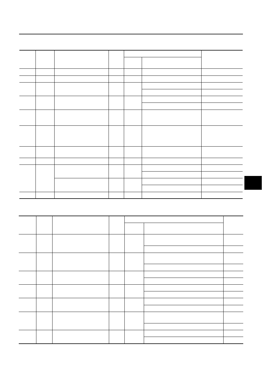
Terminals and Reference Values for Driver Side Door Mirror Control Unit 
(LCU03) and Passenger Side Door Mirror Control Unit (LCU04)

NIS000ZZ

(): Passenger side door mirror control unit.

Terminals and Reference Values for BCM 

NIS00100

Termi-

nal

Wire 

color

Signal name

Signal 

input/

output

Measuring condition

Voltage [V]

(Approx.)

Ignition 

switch

Operation or condition

1

W/L

Mirror sensor power supply

Output

ON

5

2

Y

Mirror sensor ground

ON

0

3

GY/R

(R)

Mirror motor UP signal

Output

ON

When motor is activated (UP)

Battery voltage

When motor is not activated

0

4

BR

Mirror motor LH signal

Output

ON

When motor is activated (LH)

Battery voltage

When motor is not activated

0

5

L/Y

Mirror sensor UP/ DOWN sig-
nal

Input

ON

When motor is activated 
(UP or DOWN)

Changes between 
4 (close to perk) – 

0.5 (close to valley)

6

G

Mirror sensor LH / RH signal

Input

ON

When motor is activated 
(LH or RH)

Changes between 

4 (close to right edge) 

– 

0.5 (close to left edge)

7

R/B

Data line A-2 (passenger side) 
or A-3 (driver side)

ON

8

L

Power source (Fuse)

Input

OFF

Battery voltage

9

PU/W

(OR)

Mirror motor DOWN signal

Output

ON

When motor is activated (DOWN)

Battery voltage

When motor is not activated

0

Mirror motor RH signal

Output

ON

When motor is activated (RH)

Battery voltage

When motor is not activated

0

10

B

Ground

ON

0

Termi-

nal

Wire 

color

Signal name

Signal 

input/

output

Measuring condition

Voltage 

[V]

(Approx.)

Ignition 

switch

Operation or condition

21

GY

Door mirror LH / RH switching 
signal – RH

Input

ON

Set the door mirror remote control switch to 
right position.

0

Other than above

5

24

B/OR

Door mirror LH / RH switching 
signal – LH

Input

ON

Set the door mirror remote control switch to 
left position.

0

Other than above

5

25

G/R

Door mirror remote control 
switch signal – LH operation

Input

ON

Set the either LH/RH door mirror face to left.

0

Other than above

5

29

LG/R

Door mirror remote control 
switch signal – RH operation

Input

ON

Set the either LH/RH door mirror face to right. 

0

Other than above

5

32

L/B

Door mirror remote control 
switch signal – Upward

Input

ON

Set the either LH/RH door mirror face upward.

0

Other than above

5

34

P/L

Door mirror remote control 
switch signal – Downward

Input

ON

Set the either LH/RH door mirror face down-
ward.

0

Other than above

5

39

G

Memory switch1 signal

Input

ON

Memory switch1 (ON)

0

Memory switch1 (OFF)

5

GW-90

REVERSE INTERLOCK DOOR MIRROR SYSTEM

43

OR

Memory switch2 signal

Input

ON

Memory switch2 (ON)

0

Memory switch2 (OFF)

5

50

R/Y

Set switch signal

Input

ON

Set switch (ON)

0

Set switch (OFF)

5

56

B

Ground

ON

0

61

R/B

Data line A – 2

67

G/W

Data line A – 3

105

Y/L

Power source (Fuse)

Input

OFF

Battery 
voltage

113

B

Ground

ON

0

141

R/B

R position signal

Input

ON

When the selector lever is in R position

Battery 
voltage

When the selector lever is not in R position

0

Termi-

nal

Wire 

color

Signal name

Signal 

input/

output

Measuring condition

Voltage 

[V]

(Approx.)

Ignition 

switch

Operation or condition

REVERSE INTERLOCK DOOR MIRROR SYSTEM

GW-91

C

D

E

F

G

H

J

K

L

M

A

B

GW

Work Flow

NIS00101

1.

Check the symptom and customer's requests.

2.

Understand the system description. Refer to 

GW-81, "System Description"

 .

3.

Carry out the preliminary check. Refer to 

GW-91, "Preliminary Check"

 .

4.

Carry out the communication inspection. 
If CONSULT-II is used, refer to

GW-94, "IVMS COMMUNICATION INSPECTION"

 . 

If CONSULT-II is not used, refer to 

GW-101, "COMMUNICATION DIAGNOSIS"

 . 

Is the communication diagnosis result OK?
If OK, GO TO 7.
If NG, GO TO 5.

5.

Repair or replace depending on the diagnosis result.

6.

Carry out the communication diagnosis again. 
If CONSULT-II is used, refer to 

GW-94, "IVMS COMMUNICATION INSPECTION"

 . 

If CONSULT-II is not used, refer to

GW-101, "COMMUNICATION DIAGNOSIS"

 . 

Is communication diagnosis result OK? 
If OK, GO TO 7. 
If NG, GO TO 5.

7.

Perform self-diagnosis. 
If CONSULT-II is used, refer to 

GW-93, "CONSULT-II BASIC OPERATION PROCEDURE"

 . 

If CONSULT-II is not used, refer to 

SE-50, "ON BOARD DIAGNOSIS FOR AUTOMATIC DRIVE POSI-

TIONER"

 . 

Is self-diagnosis result OK? 
If OK, GO TO 11. 
If NG, GO TO 8.

8.

Repair or replace depending on the diagnosis result.

9.

Carry out the self-diagnosis again. 
If CONSULT-II is used, refer to 

GW-93, "CONSULT-II BASIC OPERATION PROCEDURE"

 . 

If CONSULT-II is not used, 
refer to 

SE-50, "ON BOARD DIAGNOSIS FOR AUTOMATIC DRIVE POSITIONER"

 . 

Is self-diagnosis result OK? 
If OK, GO TO 11. 
If NG, GO TO 8.

10. Referring to Trouble diagnosis chart, repair or replace the cause of the malfunction. Refer to 

GW-108,

"Symptom Chart"

 .

11. Does the Reverse Interlock Door Mirror System operate normally? 

If it operates normally, GO TO 12. 
If not, GO TO 10.

12. Inspection end

Preliminary Check

NIS00102

POWER SUPPLY AND GROUND CIRCUIT INSPECTION

1. 

CHECK FUSE.

Check that any of the following fuses in BCM and door mirror control unit are blown.

NOTE:
Refer to 

GW-83, "Component Parts and Harness Connector Location"

 .

OK or NG

OK

>> GO TO 2

NG

>> If fuse is blown, make sure to eliminate cause of problem before installing new fuse.Refer to 

PG-

2, "POWER SUPPLY ROUTING"

 .

Unit

Terminal No.

Power source

Fuse No.

BCM

105

Battery power supply

3

Door Mirror Control Unit 

(Driver side & Passenger side)

8

Battery power supply

8

GW-92

REVERSE INTERLOCK DOOR MIRROR SYSTEM

2. 

POWER SUPPLY CIRCUIT INSPECTION(BCM)

1.

Turn ignition switch OFF.

2.

Disconnect BCM connector.

3.

Check voltage between BCM connector M4 terminal 105 and
ground.

OK or NG

OK

>> GO TO 3

NG

>> Repair or replace harness.

3. 

GROUND CIRCUIT INSPECTION(BCM)

Check continuity between BCM connector M4 terminal 56, 113
and ground.

OK or NG

OK

>> GO TO 4

NG

>> Repair or replace harness.

4. 

POWER SUPPLY CIRCUIT INSPECTION (DOOR MIRROR CONTROL UNIT)

1.

Disconnect door mirror control unit connector.

2.

Check voltage between door mirror control unit connector D5
(driver side), D35 (passenger side) terminal 8 and ground.

OK or NG

OK

>> GO TO 5

NG

>> Repair or replace harness.

5. 

GROUND CIRCUIT INSPECTION (DOOR MIRROR CONTROL UNIT)

Check continuity between door mirror control unit connector D5
(driver side), D35 (passenger side) terminal 10 and ground.

OK or NG

OK

>> Preliminary check is OK.

NG

>> Repair or replace harness.

105 (Y/L) – Ground

:Battery voltage

PIIA4607E

56 (B) – Ground

:Continuity should exist.

113 (B) – Ground

:Continuity should exist.

PIIA0170E

8 (L) – Ground

:Battery voltage

PIIB1983E

10 (B) – Ground

:Continuity should exist.

PIIB1984E


Content   ..  622  623  624  625   ..