Infiniti Q45. Manual - part 622
REVERSE INTERLOCK DOOR MIRROR SYSTEM
GW-81
C
D
E
F
G
H
J
K
L
M
A
B
GW
REVERSE INTERLOCK DOOR MIRROR SYSTEM
PFP:28548
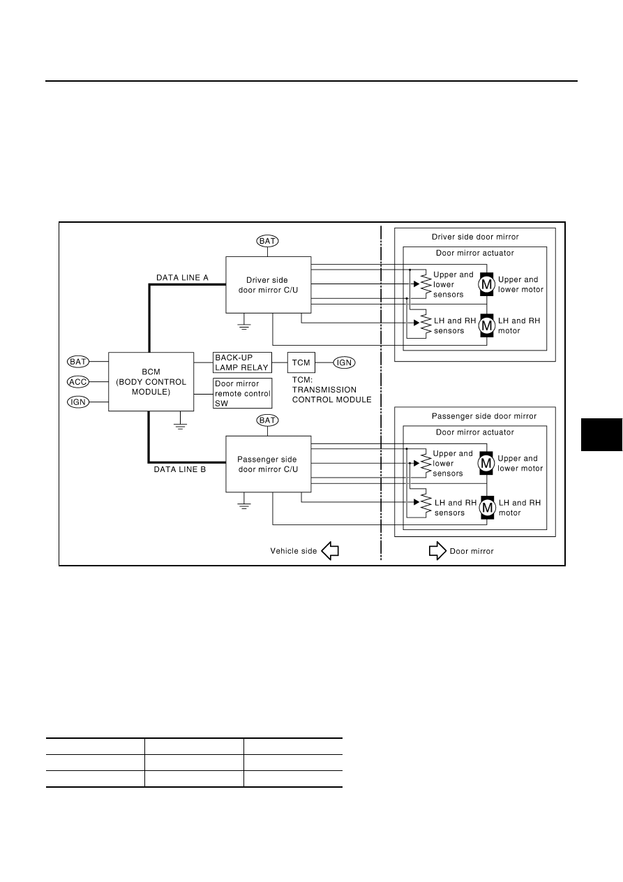
System Description
NIS000ZV
●
When switching the door mirror remote control switch position (LH/RH), the system moves driver or pas-
senger door mirror face downward, in relation to the A/T selector lever being shifted to Reverse Position.
●
The mirror position with the reverse gear engaged can be adjusted and the adjusted mirror position can
be stored in memory (2 positions).
●
With reverse gear-linked operation signal, the door mirror control unit– driver side (LCU03) / passenger
side (LCU04) installed on the door panel drives and controls the motors (UP/DOWN, LH/RH).
●
Using the self-diagnostic function and CONSULT-II, system diagnosis can be performed.
OUTLINE OF OPERATION
Operation Conditions
If all of the following conditions are satisfied, starts operating after approximately 0.5 seconds.
●
Ignition switch is in ON position.
●
Set the door mirror remote control switch from the neutral position to right position, or left position.
●
A/T selector lever is in R position.
NOTE:
●
If the conditions for reverse gear-linked operation are satisfied during manual operation, the manual oper-
ation is interrupted and switched to the reverse gear-linked operation.
Operation Angle
Fixed operation angle
PIIA0168E
Facing downward
Facing innerward
Driver-side
7
°
1
°
Passenger-side
7
°
1
°