Index Infiniti Infiniti Q45 - service repair manual 2006 year
Search copyright infringement
Content .. 616 617 618 619 ..
Infiniti Q45. Manual - part 618
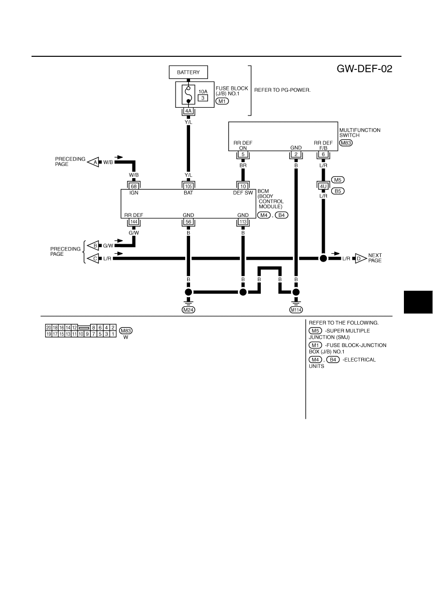
REAR WINDOW DEFOGGER
GW-65
C
D
E
F
G
H
J
K
L
M
A
B
GW
TIWM1393E