Infiniti Q45. Manual - part 611
POWER WINDOW SYSTEM
GW-37
C
D
E
F
G
H
J
K
L
M
A
B
GW
3.
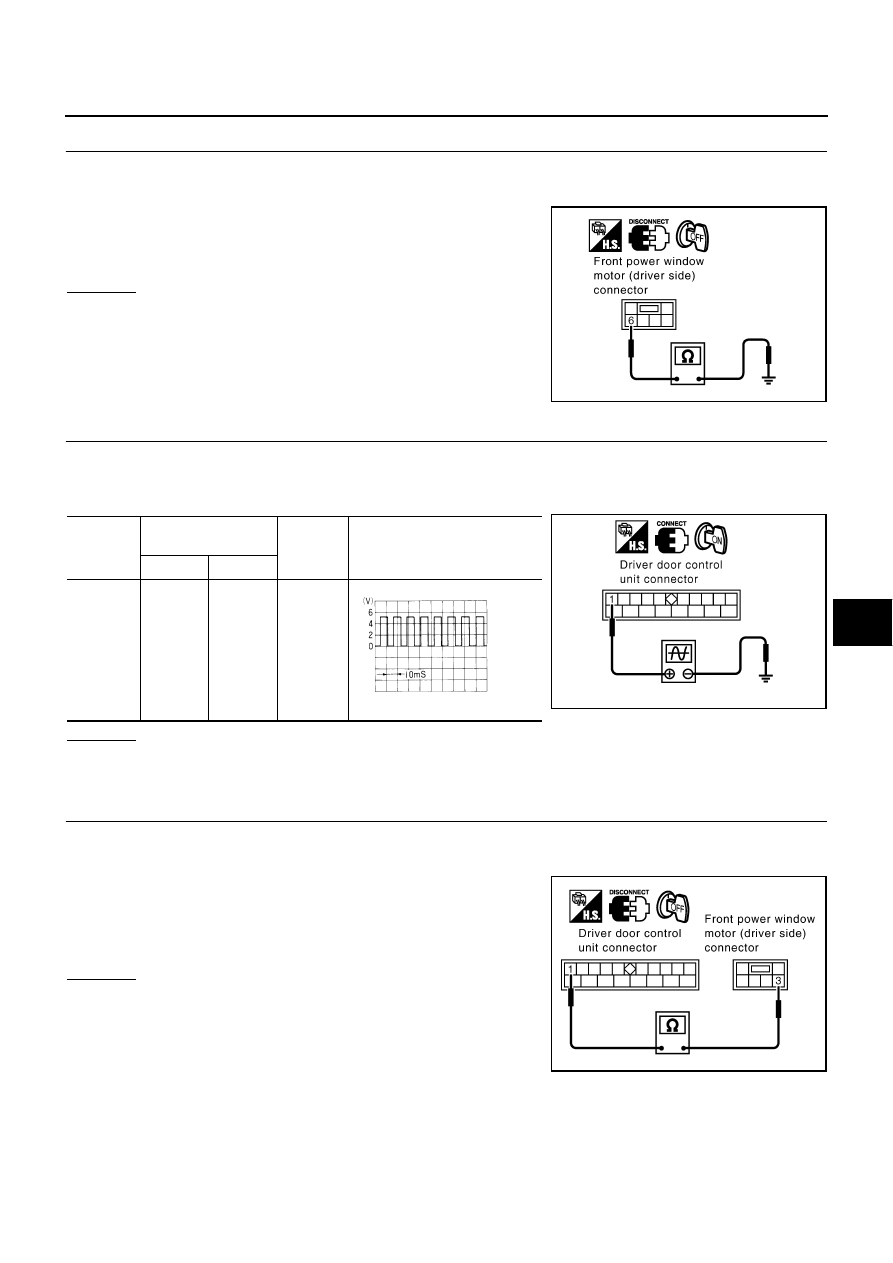
CHECK ENCODER GROUND
1.
Turn ignition switch OFF.
2.
Disconnect front power window motor (driver side) connector.
3.
Check continuity between front power window motor (driver
side) connector D7 terminal 6 and ground.
OK or NG
OK
>> GO TO 4.
NG
>> Repair or replace harness.
4.
CHECK ENCODER SIGNAL
1.
Connect front power window motor (driver side) connector.
2.
Turn ignition switch ON.
3.
Check the signal between driver door control unit (LCU01) connector and ground with oscilloscope.
OK or NG
OK
>> Encoder function is OK.
NG
>> GO TO 5
5.
CHECK ENCODER CIRCUIT
1.
Turn ignition switch OFF.
2.
Disconnect driver door control unit and front power window motor (driver side) connector.
3.
Check continuity between driver door control unit (LCU01) con-
nector D8 terminal 1 and front power window motor (driver side)
connector D7 terminal 3.
OK or NG
OK
>> Replace front power window motor (driver side).
NG
>> Repair or replace harness.
6 (B) – Ground
:Continuity should exist.
PIIB0159E
Connector
Terminals
(Wire color)
Condition
Signal
(Reference value)
(+)
(-)
D8
1 (G)
Ground
Down
PIIA2997E
OCC3383D
1 (G) – 3 (G)
:Continuity should exist.
PIIB0160E