Infiniti Q45. Manual - part 586


  Index      Infiniti     Infiniti Q45 - service repair manual 2006 year


Search            copyright infringement  


Content   ..  584  585  586  587   ..


Infiniti Q45. Manual - part 586


COIL SPRING AND STRUT

FSU-11

C

D

F

G

H

I

J

K

L

M

A

B

FSU

INSPECTION AFTER DISASSEMBLY 
Strut Inspection

Check the followings

Strut assembly for deformation, cracks, damage, and replace if necessary.

Piston rod for damage, uneven wear or distortion, and replace if necessary.

Welded and sealed areas for oil leakage, and replace if necessary.

Strut Mounting Insulator and Rubber Parts Inspection

Check mounting insulator, mounting insulator bracket for cracks and rubber parts for wear. Replace them if
necessary.

Coil Spring Inspection

Check coil spring for cracks, wear or damage and replace if necessary.

ASSEMBLY

NOTE:
Make sure strut piston rod is not damaged when attaching components to strut assembly.
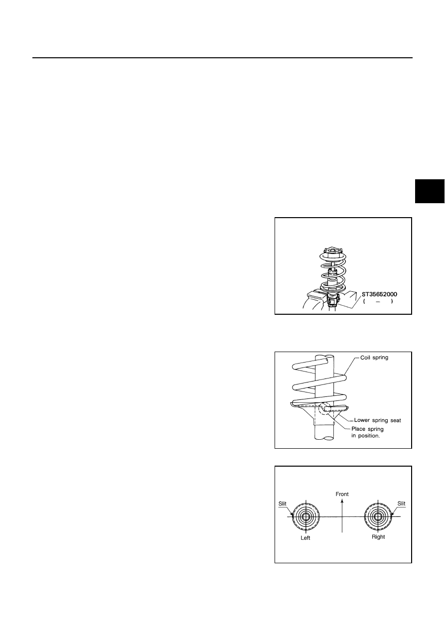
1.

Install strut attachment (SST) to strut assembly and secure it in
a vise.

CAUTION:

When installing the strut attachment (SST) to strut assem-
bly, wrap a shop cloth around strut assembly to protect it
from damage.

2.

Install lower rubber seat to strut assembly.

3.

Compress coil spring using a spring compressor (commercial service tool), and install it onto strut assem-
bly.

CAUTION:

Face the tube side of coil spring downward. Align lower
end to spring seat as shown in the figure.

Be sure spring compressor (commercial service tool) is
securely attached to coil spring. And then compress coil
spring.

4.

Apply soapy water to bound bumper, lnsert bound bumper into
spring upper seat, and then install it to strut together with upper
rubber seat.

CAUTION:

Do not use machine oil.

Installation position of spring upper seat as shown in the
figure.

5.

Install strut mounting insulator assembly, strut mounting bracket
and gasket to strut.

SEIA0296E

SFA149

SEIA0247E

FSU-12

COIL SPRING AND STRUT

6.

Fix strut mounting insulator, then tighten piston rod lock nut with
the specified torque.

CAUTION:

Be careful not to deform strut mounting insulator.

7.

Gradually release spring compressor (commercial service tool),
and remove coil spring.

CAUTION:

Loosen spring compressor while making sure coil spring
attachment position does not move.

8.

Remove strut attachment (SST) from strut assembly.

9.

Install actuator plate onto strut assembly.(with active damper
suspension)

10. Fix strut mounting insulator, then tighten actuator plate fixing nut with the specified torque.(with active

damper suspension)

CAUTION:

Be careful not to deform actuator plate and strut mounting insulator.

SFA261B

SUSPENSION ARM

FSU-13

C

D

F

G

H

I

J

K

L

M

A

B

FSU

SUSPENSION ARM

PFP:55501

Removal and Installation

NES0006A

REMOVAL

1.

Remove tires from vehicle with power tool.

2.

Remove undercover with power tool.

3.

Remove cotter pin of suspension arm and strut assembly, and then loosen nut.

4.

Use the ball joint remover (suitable tool) to remove suspension arm from strut assembly. Be careful not to
damage ball joint boot.

CAUTION:

Tighten temporarily mounting nut to prevent damage to threads and to prevent the ball joint
remover (suitable tool) from coming off.

5.

Remove fixing bolts, washer and nuts then remove suspension arm from vehicle.

INSPECTION AFTER REMOVAL 
Visual Inspection

Check suspension arm and bushing for deformation, cracks, or damage. If any non-standard condition is
found, replace it.

Check boot of ball joint for cracks, or other damage, and also for grease leakage. If any non-standard con-
dition is found, replace it.

Ball Joint Inspection

Manually move ball stud to confirm it moves smoothly with no binding.

Swing Torque Inspection

NOTE:
Before measurement, move ball joint at least ten times by hand to check for smooth movement.

Hook spring balance at cotter pin mounting hole. Confirm spring
balance measurement value is within the specifications when
ball stud begins moving.

If it is outside the specified range, replace suspension arm
assembly.

Rotating Torque Inspection

Attach mounting nut to ball stud. Check that rotating torque is
within the specifications with a preload gauge (SST).

If it is outside the specified range, replace suspension arm
assembly.

Axial End Play Inspection

Move the tip of ball joint in the axial direction to check for looseness.

If it is outside the specified range, replace suspension arm assembly.

Specified swing torque:

           0.5 - 3.4 N·m (0.06 - 0.34 kg-m, 5 - 30 in-lb)

Specified value of spring balance:

           8.8 - 59.6 N (0.90 - 6.08 kg, 1.98 - 13.41 lb)

SEIA0523E

Specified rotating torque:

            0.5 - 3.4 N·m (0.06 - 0.34 kg-m, 5 - 30 lb)

SDIA1150E

Specified axial end play

: 0 mm (0 in)

FSU-14

SUSPENSION ARM

INSTALLATION

Refer to 

FSU-7, "Components"

  for tightening torque. Install in the reverse order of the removal.

NOTE:
Refer to component parts location and do not reuse non-reusable parts.

After removing/installing or replacing suspension components, check wheel alignment. Refer to 

FSU-5,

"Wheel Alignment Inspection"

 .

After adjusting wheel alignment, adjust neutral position of steering angle sensor. Refer to 

BRC-6, "Adjust-

ment of Steering Angle Sensor Neutral Position"

 .


Content   ..  584  585  586  587   ..