Infiniti Q45. Manual - part 584


  Index      Infiniti     Infiniti Q45 - service repair manual 2006 year


Search            copyright infringement  


Content   ..  582  583  584  585   ..


Infiniti Q45. Manual - part 584


PREPARATION

FSU-3

C

D

F

G

H

I

J

K

L

M

A

B

FSU

PREPARATION

PFP:00002

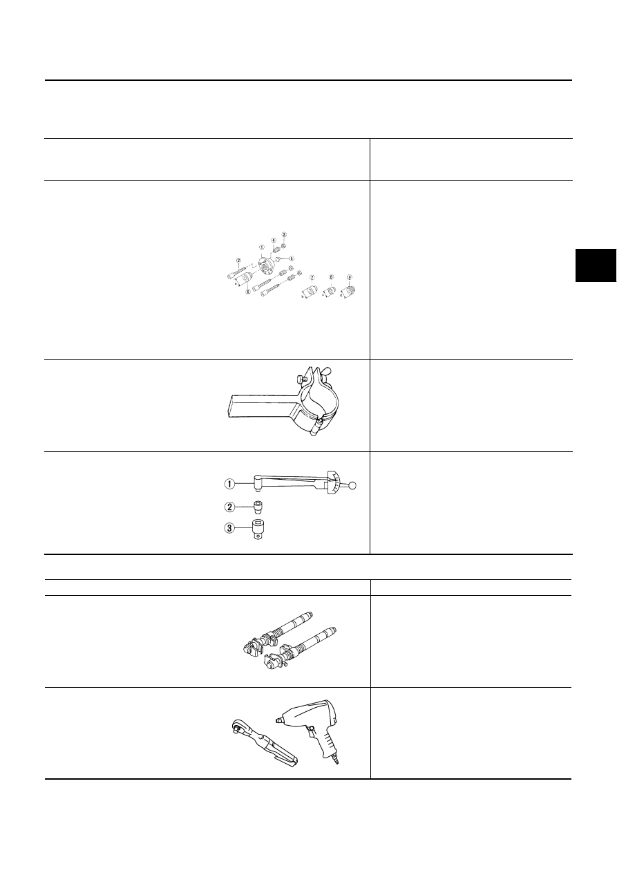
Special Service Tools (SST)

NES00062

The actual shapes of Kent-Moore tools may differ from those of special service tools illustrated here.

Commercial Service Tools

NES00063

Tool number
 (Kent-Moore No.)
Tool name

Description

KV991040S0 
(


)

CCK gauge attachment
 1.Plate
 2.Guide bolts
 3.Nuts
 4.Springs
 5.Center plate
 6.KV99104020 Adapter A 
    a: 72 mm (2.83 in) dia.
 7.KV99104030 Adapter B 
    b: 65 mm (2.56 in) dia.
 8.KV99104040 Adapter C 
    c: 57 mm (2.24 in) dia.
 9.KV99104050 Adapter D 
    d: 53.4 mm (2.102 in) dia.

Measuring wheel alignment

ST35652000
(


)

Strut attachment

Disassembling and assembling strut

ST3127S000
(See J

25765-A)

Preload gauge
1. GG91030000
              Torque wrench (J

25765)

2. HT62940000 (    —    )
              Socket adapter (1/2

)

3. HT62900000 (    —    )
              Socket adapter (3/8

)

Measuring rotating torque of ball joint

S-NT498

ZZA0807D

NT124

 Tool name

Description

Spring compressor

Removing coil spring

Power tool

Removing wheel nuts

Removing undercover

Removing brake caliper assembly

Removing suspension components parts

S-NT717

PBIC0190E

FSU-4

NOISE, VIBRATION AND HARSHNESS (NVH) TROUBLESHOOTING

NOISE, VIBRATION AND HARSHNESS (NVH) TROUBLESHOOTING

PFP:00003

NVH Troubleshooting Chart

NES00064

Use chart below to help you find the cause of the symptom. If necessary, repair or replace these parts.

×

: Applicable

Reference page

FSU-

7

FSU-

1

1

FSU-

7

FSU-

5

FSU-

15

NVH in

 PR s

e

c

ti

o

n

NVH in

 RFD s

e

c

ti

o

n

.

N

V

H

 i

n

 F

AX and FSU

 sect

io

ns

.

NVH i

n

 W

T

 s

e

c

tio

n

.

NVH i

n

 W

T

 s

e

c

tio

n

.

NVH in

 RAX s

e

c

ti

o

n

.

NVH 

in

 BR s

e

c

tio

n

.

NVH 

in

 PS s

e

c

tio

n

.

Possible cause and SUSPECTED PARTS

Im

pr

ope

r i

n

st

al

la

ti

on,

 l

o

o

s

ene

ss

S

tr

u

t de

fo

rm

at

io

n,

 da

m

a

ge 

or

 de

fl

ect

ion

Bush

in

o

r m

ount

ing det

er

io

ra

ti

o

n

Par

ts

 i

n

te

rf

er

enc

e

Sp

ri

n

g

 fa

tig

u

e

Susp

ensi

o

n

 l

oos

enes

s

In

cor

rec

t w

hee

l al

ig

nm

ent

S

tab

ili

z

er

 ba

fa

ti

gue

PROPELLER SHAFT

DI

F

F

ERENTI

AL

FRONT A

X

LE 

AND FRONT 

SUSPENSION

TIRES

ROAD W

H

EELS

DRI

VE SHAFT

BRAKES

STEERING

Symptom

FRONT SUSPENSION

Noise

× ×

×

×

×

×

×

× ×

×

×

× ×

×

Shake

× ×

×

×

×

×

×

×

×

× ×

×

Vibration

× ×

×

×

×

×

×

×

×

×

Shimmy

× ×

×

×

×

×

×

×

×

×

Judder

× ×

×

×

×

×

×

×

Poor quality ride or han-
dling

× ×

×

×

×

× ×

×

×

×

FRONT SUSPENSION ASSEMBLY

FSU-5

C

D

F

G

H

I

J

K

L

M

A

B

FSU

FRONT SUSPENSION ASSEMBLY

PFP:54010

On-Vehicle Inspection and Service

NES00065

Make sure the mounting conditions (looseness, back lash) of each component and component conditions
(wear, damage) are normal.

INSPECTION LOWER BALL JOINT END PLAY

1.

Set front wheels in a straight-ahead position. Do not depress brake pedal.

2.

Place an iron bar or similar tool between transverse link and steering knuckle.

3.

Measure axial end play by prying it up and down.

CAUTION:

Be careful not to damage ball joint boot.

STRUT INSPECTION

Check strut for oil leakage, damage and replace if there are. Refer to 

FSU-8, "COIL SPRING AND

STRUT"

 .

Wheel Alignment Inspection

NES000HL

DESCRIPTION

Measure wheel alignment under unladen conditions.

NOTE:
Unladen conditions mean that fuel, engine coolant, and lubricant are full. Spare tire, jack, hand tools and
mats are designated positions.

PRELIMINARY CHECK

Check tires for improper air pressure and wear.

Check road wheels for runout.

Check wheel bearing axial end play.

Check ball joint axial end play of compression rod, upper link, and steering knuckle 

Check shock absorber operation.

Check each mounting part of axle and suspension for looseness and deformation.

Check each link, rod and member for cracks, deformation and other damage.

Check vehicle posture.

GENERAL INFORMATION AND RECOMMENDATIONS

A four-wheel thrust alignment should be performed.

This type of alignment is recommended for any NISSAN/INFINITI vehicle.

The four-wheel “thrust” process helps ensure that the vehicle is properly aligned and the steering wheel is
centered.

The alignment rack itself should be capable of accepting any NISSAN/INFINITI vehicle.

The rack should be checked to ensure that it is level.

Make sure the machine is properly calibrated.

Your alignment equipment should be regularly calibrated in order to give correct information.

Check with the manufacturer of your specific equipment for their recommended Service/Calibration
Schedule.

Axial end play

: 0 mm (0 in)

FSU-6

FRONT SUSPENSION ASSEMBLY

THE ALIGNMENT PROCESS

IMPORTANT:
Use only the alignment specifications listed in this Service Manual.

When displaying the alignment settings, many alignment machines use “indicators”: (Green/red, plus or
minus, Go/No Go). Do NOT use these indicators.

The alignment specifications programmed into your machine that operate these indicators may not be cor-
rect.

This may result in an ERROR.

Some newer alignment machines are equipped with an optional “Rolling Compensation” method to “com-
pensate” the sensors (alignment targets or head units). DO NOT use this “Rolling Compensation”
method.

Use the “Jacking Compensation Method”. After installing the alignment targets or head units, raise the
vehicle and rotate the wheels 1/2 turn both ways.

See Instructions in the alignment machine you're using for more information on this.

INSPECTION OF CAMBER, CASTER AND KINGPIN INCLINATION ANGLES

Camber, caster, kingpin inclination angles cannot be adjusted.

Before inspection, mount front wheels onto turning radius gauge. Mount rear wheels onto a stand that has
same height so vehicle will remain horizontal.

Using a CCK Gauge

Install CCK gauge attachment [SST: KV991040S0 ( – )] as following procedure in wheel, then measure
wheel alignment.

1.

Remove wheel nuts (2), and install a guide bolts to hub bolts.

2.

Screw adapter into plate body until it contacts plate tightly.

3.

Screw center plate into plate.

4.

Insert plate on guide bolts. Put spring in, and then evenly screw
both guide bolt nuts. When fastening guide nuts, do not com-
pletely compress springs.

5.

Place the dent of alignment gauge onto the projection of center
plate and tightly contact them to measure.

CAUTION:

If camber, caster, or kingpin inclination angle is outside
the standard, check front suspension parts for wear and
damage, and replace suspect parts if necessary.

King pin inclination angle is reference value, no inspection is required. (Due to the type of sus-
pension, the kingpin inclination angle cannot be measured correctly using a normal alignment
tester.)

SEIA0240E

Standard value

Camber, caster, kingpin inclination angles:

Refer to 

FSU-17, "SERVICE DATA AND SPECIFI-

CATIONS (SDS)"

 .

SEIA0241E


Content   ..  582  583  584  585   ..