Infiniti Q45. Manual - part 560


  Index      Infiniti     Infiniti Q45 - service repair manual 2006 year


Search            copyright infringement  


Content   ..  558  559  560  561   ..


Infiniti Q45. Manual - part 560


CAMSHAFT

EM-57

C

D

E

F

G

H

I

J

K

L

M

A

EM

3.

Remove intake valve timing control solenoid valve. Refer to 

EM-39, "TIMING CHAIN"

  .

4.

Crank the engine, and then make sure that engine oil comes out
from intake valve timing control cover oil hole. End crank after
checking.

WARNING:

Be careful not to touch rotating parts (drive belt, idler pul-
ley, and crankshaft pulley, etc.).

CAUTION:

Engine oil may squirt from intake valve timing control sole-
noid valve installation hole during cranking. Use a shop
cloth to prevent the engine components and the vehicle. Do
not allow engine oil to get on rubber components such as
drive belt or engine mount insulators. Immediately wipe off
any splashed engine oil.

Clean oil groove between oil strainer and intake valve timing control solenoid valve if engine oil does not
come out from intake valve timing control cover oil hole. Refer to 

LU-4, "LUBRICATION SYSTEM"

  .

5.

Remove components between intake valve timing control solenoid valve and camshaft sprocket (INT),
and then check each oil groove for clogging.

Clean oil groove if necessary. Refer to 

LU-4, "LUBRICATION SYSTEM"

  .

6.

After inspection, install removed parts.

Valve Clearance

NBS001OT

INSPECTION

Perform inspection as follows after removal, installation or replacement of camshaft or valve-related parts, or if
there is unusual engine conditions due to changes in valve clearance (engine starting, idling, and/or noise). 

1.

Remove rocker cover (right and left bank) with power tool. Refer to 

EM-37, "Removal and Installation"

 .

2.

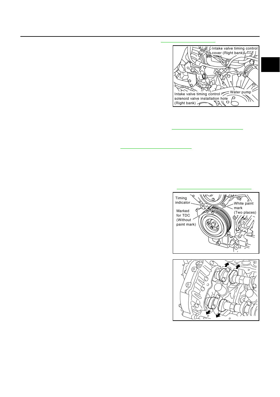
Turn crankshaft pulley in normal direction (clockwise when
viewed from engine front) to align TDC identification notch (with-
out paint mark) with timing indicator.

3.

At this time, make sure that the both intake and exhaust cam
noses of No. 1 cylinder (top front on left bank) face outside.

If they do not face outside, turn crankshaft pulley by 360
degrees once more.

PBIC2848E

PBIC2341E

KBIA0400J

EM-58

CAMSHAFT

4.

Measure the clearance between valve lifter and camshaft with a
feeler gauge.

Valve clearance:

Unit: mm (in)

*:Approximately 80

°

C (176

°

F)

5.

By referring to the figure, measure valve clearances at locations
marked X as shown in the table below (locations indicated with
black arrow in figure) with a feeler gauge.
NOTE:
Firing order 1-8-7-3-6-5-4-2

No.1 cylinder compression TDC

6.

Turn crankshaft pulley clockwise by 270 degrees from the posi-
tion of No. 1 cylinder compression TDC to obtain No. 3 cylinder
compression TDC. 

SEM139D

Cold

Hot * (reference data)

Intake

0.26 - 0.34 (0.010 - 0.013)

0.304 - 0.416 (0.012 - 0.016)

Exhaust

0.29 - 0.37 (0.011 - 0.015)

0.308 - 0.432 (0.012 - 0.017)

Measuring position (Right bank)

No. 2 CYL

No. 4 CYL

No. 6 CYL

No. 8 CYL

No. 1 cylinder at TDC

 EXH


×

INT

×

×


Measuring position (Left bank)

No. 1 CYL

No. 3 CYL

No. 5 CYL

No. 7 CYL

No. 1 cylinder at TDC

INT

×

×


EXH

×

×

PBIC0823E

PBIC0065E

CAMSHAFT

EM-59

C

D

E

F

G

H

I

J

K

L

M

A

EM

7.

By referring to the figure, measure valve clearances at locations
marked X as shown in the table below (locations indicated with
white arrow in figure). 

No.3 cylinder compression TDC.

8.

Rotate crankshaft pulley clockwise (when view from engine
front) by 90 degrees from the position of No. 3 cylinder compres-
sion TDC to align No. 6 cylinder at TDC of its compression
stroke. 

By referring to the figure, measure valve clearances at loca-
tions marked “

×

” as shown in the table below. 

No. 6 cylinder compression TDC

9.

For measured value are out of standard, perform adjustment. Refer to 

EM-60, "ADJUSTMENT"

 .

Measuring position (Right bank)

No. 2 CYL

No. 4 CYL

No. 6 CYL

No. 8 CYL

No. 3 cylinder at TDC

 EXH


×

INT


×

Measuring position (Left bank)

No. 1 CYL

No. 3 CYL

No. 5 CYL

No. 7 CYL

No. 3 cylinder at TDC

INT

×

×


EXH

×

×

PBIC0823E

PBIC2346E

Measuring position (Right bank)

No. 2 CYL

No. 4 CYL

No. 6 CYL

No. 8 CYL

No. 6 cylinder at TDC

 EXH

×


×

INT


×

PBIC0824E

EM-60

CAMSHAFT

ADJUSTMENT

NOTE:
Adjust valve clearance while engine is cold.
1.

Turn crankshaft, to position cam nose on camshaft that must be
adjusted upward.

2.

Thoroughly wipe off engine oil around adjusting shim using a
rag.

3.

Using a extra-fine screwdriver, turn the round hole of the adjust-
ing shim in the direction of the arrow.

CAUTION:

Perform (the above procedure) while camshaft do not con-
tact with adjusting shim.

4.

Compress valve spring by snapping camshaft using the cam-
shaft pliers (SST), by pulling camshaft to the same direction of
the arrow and by pushing valve lifter down.

CAUTION:

Be careful not to damage cam surface with the camshaft pli-
ers.

5.

Place the lifter stopper (SST) between camshaft and the edge of
valve lifter to retain valve lifter.

CAUTION:

The lifter stopper must be placed as close to camshaft
bracket as possible.

Be careful not to damage cam surface with the lifter stop-
per.

6.

Remove the camshaft pliers (SST).

CAUTION:

When returning the camshaft pliers quickly, the lifter stopper (SST) hit and damages the journal
portion of camshaft. Therefore turn the camshaft pliers slowly.

7.

Blow air into the hole to separate adjusting shim from valve lifter.

CAUTION:

When blowing, use goggles to protect your eye.

PBIC0047E

PBIC2276E

PBIC1565E

PBIC1566E


Content   ..  558  559  560  561   ..