Infiniti Q45. Manual - part 556


  Index      Infiniti     Infiniti Q45 - service repair manual 2006 year


Search            copyright infringement  


Content   ..  554  555  556  557   ..


Infiniti Q45. Manual - part 556


TIMING CHAIN

EM-41

C

D

E

F

G

H

I

J

K

L

M

A

EM

6.

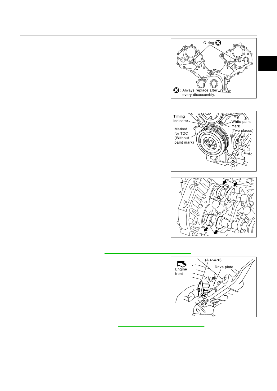
Remove O-ring from front cover.

7.

Obtain compression TDC of No. 1 cylinder as follows:

a.

Turn crankshaft pulley clockwise to align the TDC identification
notch (without paint mark) with timing indicator on front cover. 

b.

At this time, make sure the both intake and exhaust cam noses
of No.1 cylinder (top front on left bank) face outside.

If they do not face outside, turn crankshaft pulley by 360
degrees once more.

8.

Remove crankshaft pulley as follows:

a.

Remove rear plate cover. Refer to 

EM-26, "OIL PAN AND OIL STRAINER"

 .

b.

Set the ring gear stopper (SST). 

c.

Loosen crankshaft pulley bolt.

d.

Pull crankshaft pulley with both hands to remove it.

CAUTION:

Do not remove crankshaft pulley bolt. Keep loosened
crankshaft pulley bolt in place to protect removed crank-
shaft pulley from dropping.

Do not remove balance weight (inner hexagon bolt) at the
front of crankshaft pulley.

9.

Remove oil pan and oil strainer. Refer to 

EM-26, "OIL PAN AND OIL STRAINER"

 .

SBIA0374E

PBIC2341E

KBIA0400J

PBIC1656E

EM-42

TIMING CHAIN

10. Remove front cover as follows:

a.

Loosen and remove fixing bolts in the reverse order of that
shown in figure.

b.

Use the seal cutter [SST: KV10111100 (J-37228)] or the equiva-
lent to cut liquid gasket for removal. 

CAUTION:

Be careful not to damage mating surfaces.

11. Remove front oil seal from front cover using suitable tool.

CAUTION:

Be careful not to damage front cover.

12. Remove O-rings from cylinder heads (right and left bank) and

cylinder block.

13. Remove chain tensioner cover from front cover.

Use seal cutter (SST: KV10111100) or equivalent to cut liquid gasket for remove.

14. Remove oil pump drive spacer.

Install bolts into two bolt holes [M6 x pitch 1.0 mm (0.04 in)]
on front surface. Using a small puller, pull spacer off from
crankshaft. 

NOTE:
The center to center dimension between the two bolt holes is 33
mm (1.30 in).

15. Remove oil pump. Refer to 

LU-10, "OIL PUMP"

 .

16. Remove chain tensioner (left bank) as follows:

NOTE:
To remove timing chain and associated parts, start with those on left bank. The procedure for removing
parts on right bank is omitted because it is the same as that for left bank. 

a.

Press tab in the direction of arrow (or turn lever in the direction
of arrow) to unlock the locking with the groove that stops
tensioner plunger from returning.

Lightly press tensioner plunger to release the tension of
spring for this operation.

b.

Push in tensioner plunger to align the hole on lever and that on
pump main body.

Pushing in tensioner plunger too far does not allow the holes
to align. Therefore, push in the plunger to the degree at which
the start of stopper groove and tab engages.

KBIA0354J

SBIA0373E

PBIC0054E

PBIC2343E

TIMING CHAIN

EM-43

C

D

E

F

G

H

I

J

K

L

M

A

EM

c.

Insert a stopper pin [hard wire with approx. 0.5 mm (0.020 in) diameter or a similar tool] to fix plunger. With
the plunger fixed, remove chain tensioner.

17. Remove chain tension guide and chain slack guide.

18. Remove timing chain and crankshaft sprocket.
19. With hexagonal part of camshaft locked with wrench, loosen

bolts securing camshaft sprocket to remove camshaft sprocket.

CAUTION:

To avoid interference between valves and pistons, do not
turn crankshaft or camshaft with timing chain is discon-
nected.

20. Using the same procedure as for left bank, remove timing chain and associated parts on right side.

21. Use scraper to remove all traces of old liquid gasket from front cover and opposite mating surfaces.

Remove old liquid gasket from bolt hole and thread.

INSPECTION AFTER REMOVAL

Check for cracks and any excessive wear at roller links and link
plates. Replace timing chain if necessary.

PBIC0030E

PBIC2084E

PBIC0282E

EM-44

TIMING CHAIN

INSTALLATION

NOTE:

The above figure shows the relationship between the mating mark on each timing chain and that on the
corresponding sprocket, with the components installed.

Parts with an identification mark (R or L) should be installed on the corresponding bank according to the
mark. 

Parts with an identification mark:

Camshaft sprocket (INT)

Dowel pin groove of camshaft sprocket (EXH) (camshaft sprocket is same part both banks)

Chain tension guide

Chain slack guide

To install timing chain and associated parts, start with those on right bank. The procedure for installing parts on
left bank is omitted because it is the same as that for installation on right bank.

1.

Make sure that crankshaft key and dowel pin of each camshaft
are facing in the direction indicated.(No.1 cylinder at compres-
sion TDC.)

NOTE:
Camshaft does not stop at the position as shown in the figure,
for the placement of cam nose. However it is generally accepted
camshaft is placed for the same direction of the figure.

PBIC2344E

Camshaft dowel pin

: At cylinder head upper face side in each bank.

Crankshaft Key

: At cylinder head side of left bank.

SBIA0356E


Content   ..  554  555  556  557   ..