Infiniti Q45. Manual - part 552
EXHAUST MANIFOLD AND THREE WAY CATALYST
EM-25
C
D
E
F
G
H
I
J
K
L
M
A
EM
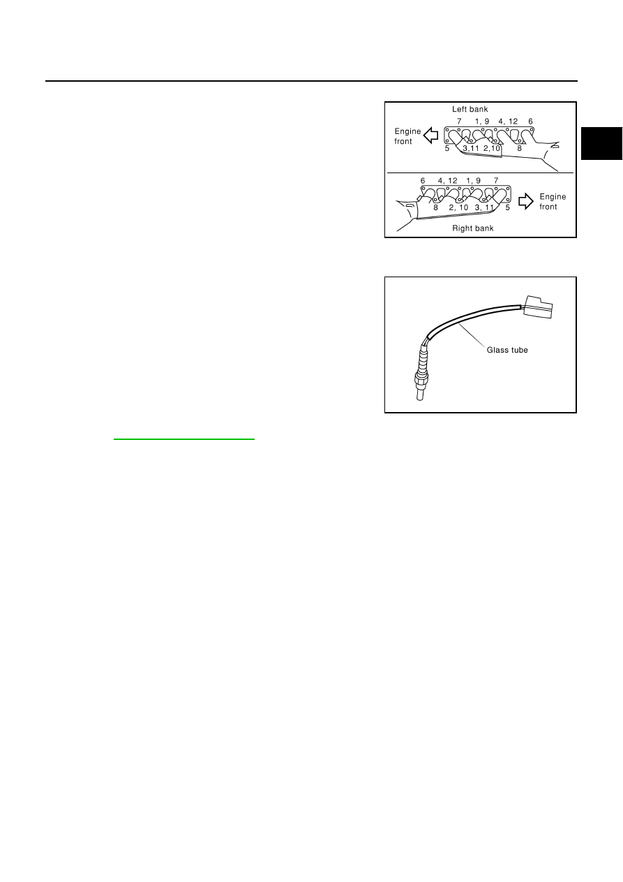
Exhaust Manifold
●
Install exhaust manifold and three way catalyst in numerical
order shown in the figure.
●
Tighten nuts No. 1 to No. 4 in two steps. Order No. 9 to 12
shows second step.
Air Fuel Ratio sensor 1 and Heated Oxygen Sensor 2
●
Install air fuel ratio sensor and heated oxygen sensors in the original position.
●
Install referring the following if the installation positions cannot
be identified.
*
1
: Length of bank1 for air fuel ratio sensor is different from
bank2.
*
2
: Refer to
CAUTION:
●
Before installing a new air fuel ratio sensor 1 and a new heated oxygen sensor 2, clean exhaust
system threads using the heated oxygen sensor thread cleaner (commercial service tool: J-43897-
18 or J-43897-12), and apply anti-seize lubricant (commercial service tool).
●
Do not over torque the air fuel ratio sensor 1 and heated oxygen sensor 2. Doing so may cause
damage to the air fuel ratio sensor 1 and heated oxygen sensor 2, resulting in the MIL coming on.
PBIC0022E
Glass tube color
Air fuel ratio sensor 1 (bank 1)*
1
: Black
Air fuel ratio sensor 1 (bank 2)*
1
: Black
Heated oxygen sensor 2 (bank 1)*
2
: White
Heated oxygen sensor 2 (bank 2)*
2
: White
PBIC2652E