Index Infiniti Infiniti Q45 - service repair manual 2006 year
Search copyright infringement
Content .. 519 520 521 522 ..
Infiniti Q45. Manual - part 521
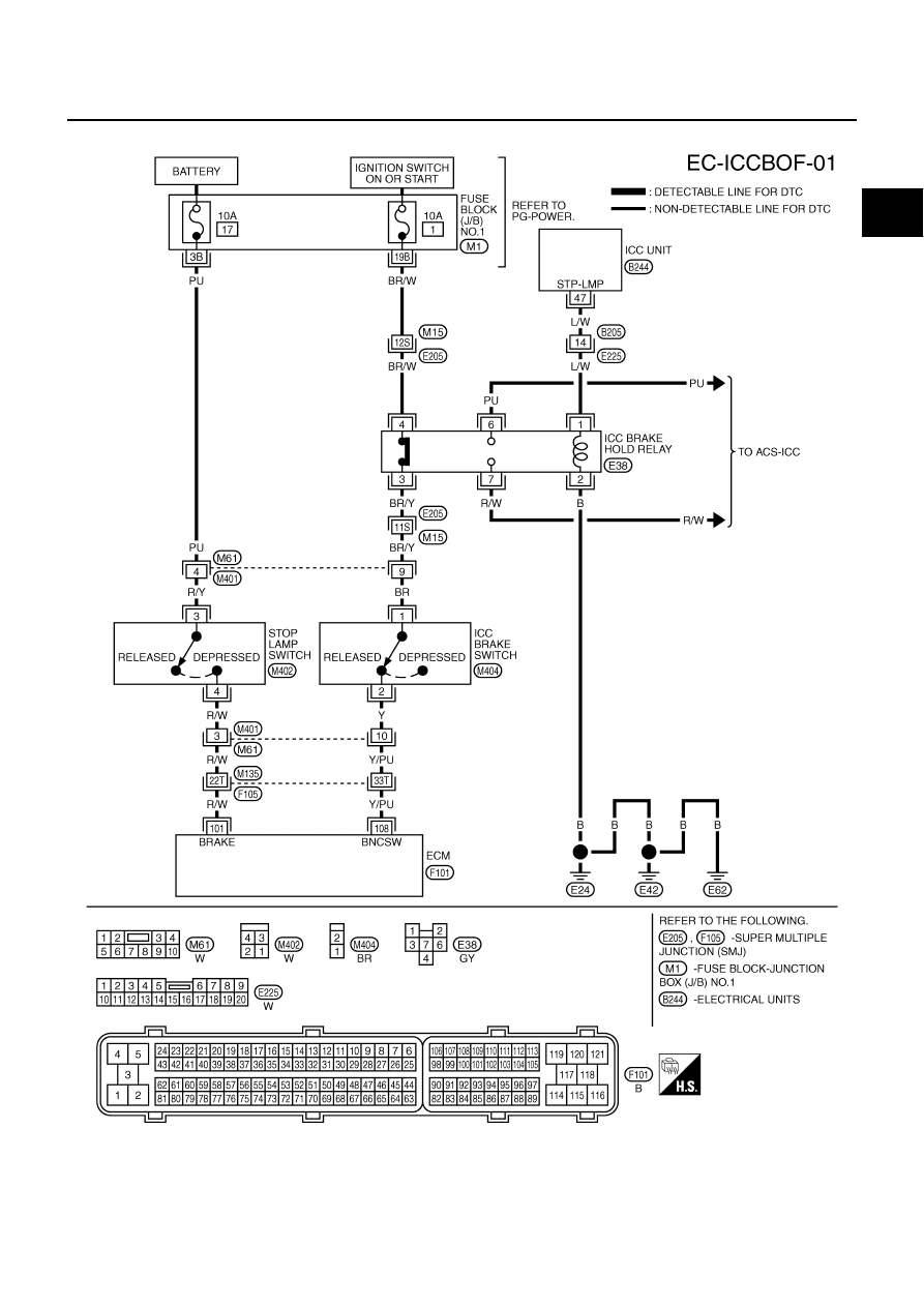
ICC BRAKE SWITCH
EC-723
C
D
E
F
G
H
I
J
K
L
M
A
EC
Wiring Diagram
NBS0027P
TBWM1259E