Index Infiniti Infiniti Q45 - service repair manual 2006 year
Search copyright infringement
Content .. 494 495 496 497 ..
Infiniti Q45. Manual - part 496
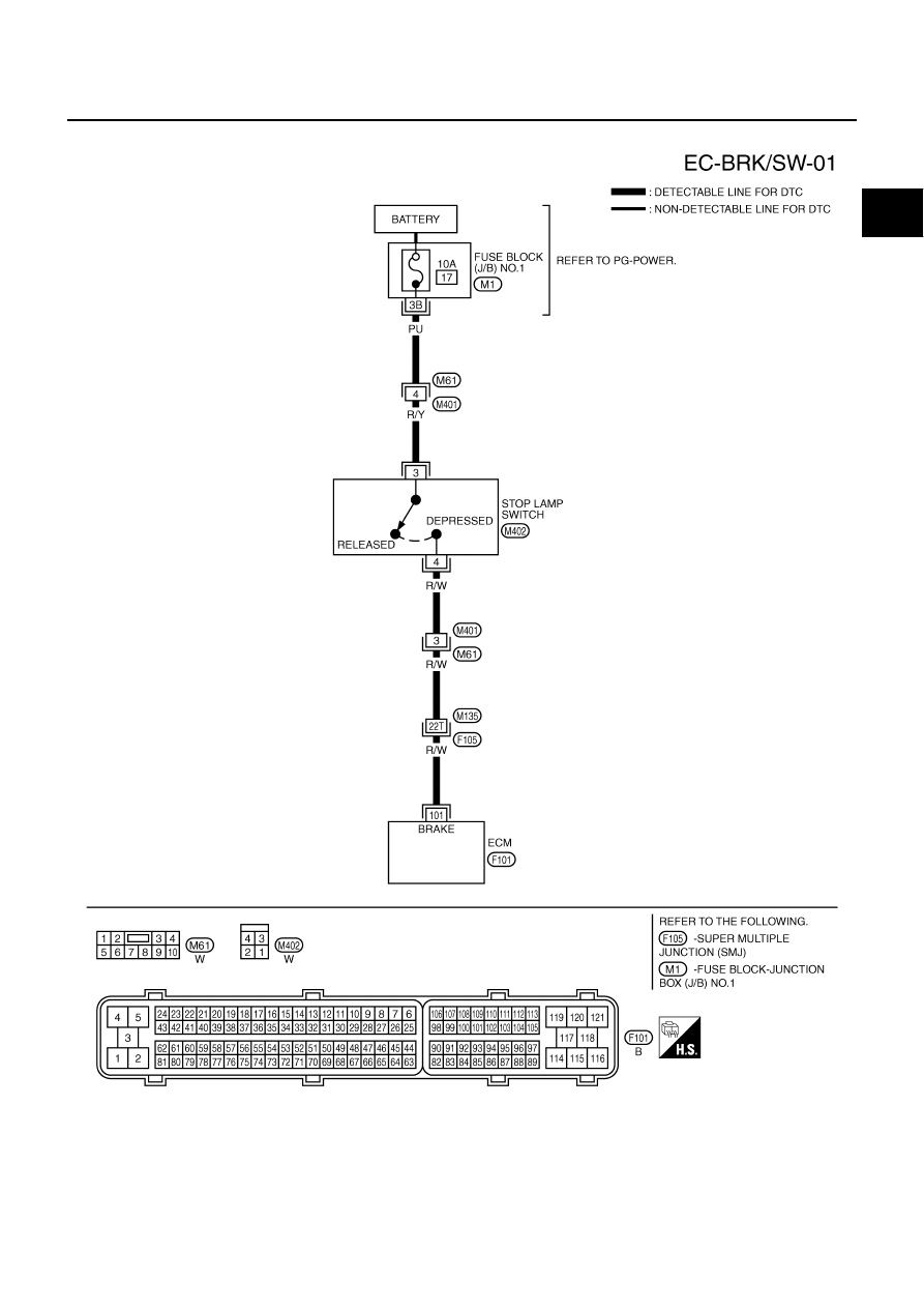
DTC P1805 BRAKE SWITCH
EC-623
C
D
E
F
G
H
I
J
K
L
M
A
EC
Wiring Diagram
NBS0025U
TBWM1249E