Infiniti Q45. Manual - part 495
DTC P1800 VIAS CONTROL SOLENOID VALVE
EC-619
C
D
E
F
G
H
I
J
K
L
M
A
EC
Specification data are reference values and are measured between each terminal and ground.
CAUTION:
Do not use ECM ground terminals when measuring input/output voltage. Doing so may result in dam-
age to the ECM's transistor. Use a ground other than ECM terminals, such as the ground.
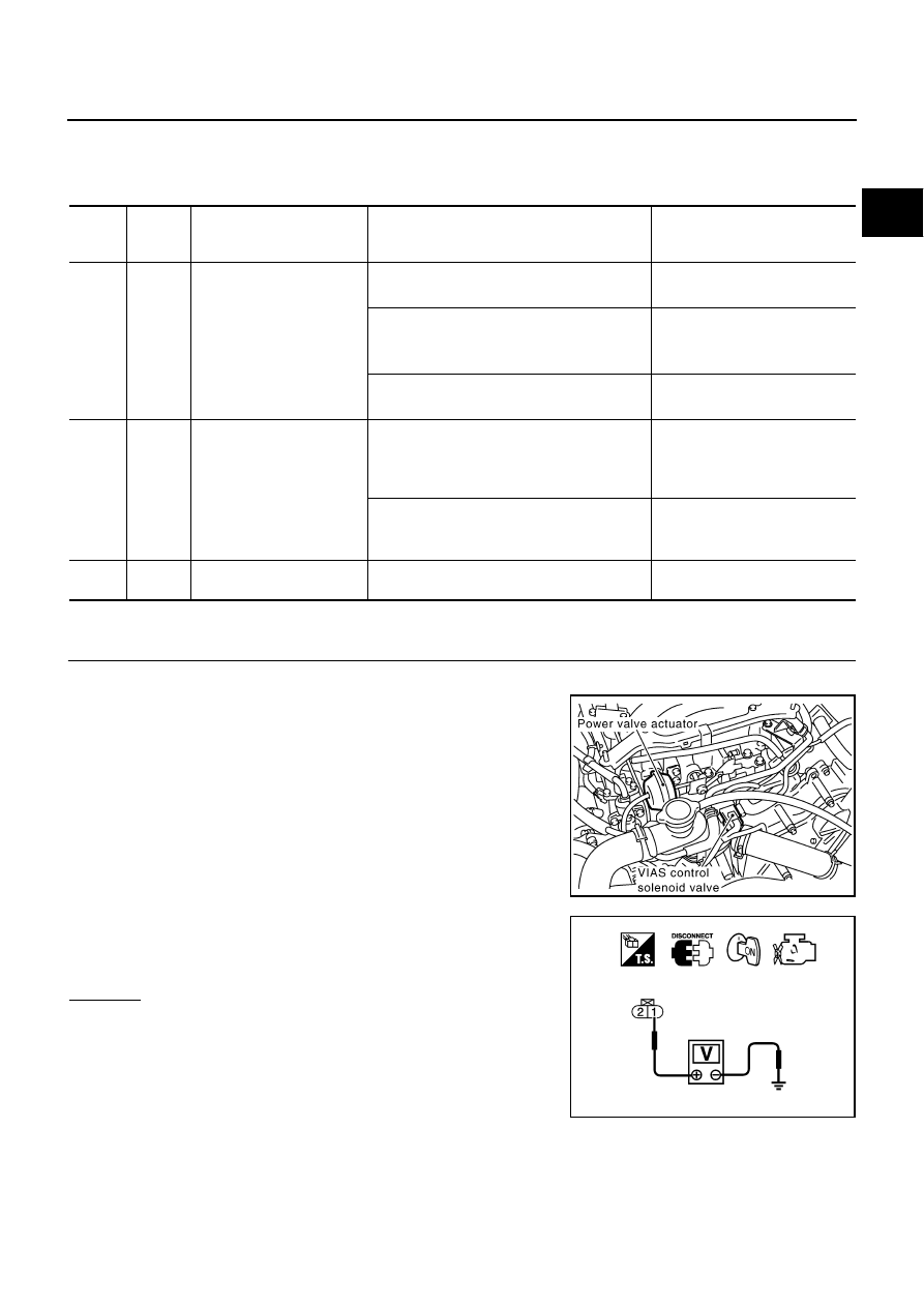
Diagnostic Procedure
NBS0025N
1.
CHECK VIAS CONTROL SOLENOID VALVE POWER SUPPLY CIRCUIT
1.
Turn ignition switch OFF.
2.
Disconnect VIAS control solenoid valve harness connector.
3.
Turn ignition switch ON.
4.
Check voltage between VIAS control solenoid valve terminal 1
and ground with CONSULT-II or tester.
OK or NG
OK
>> GO TO 3.
NG
>> GO TO 2.
TER-
MINAL
NO.
WIRE
COLOR
ITEM
CONDITION
DATA (DC Voltage)
29
PU
VIAS control solenoid valve
[Engine is running]
●
Selector lever: P or N
0 - 1.0V
[Engine is running]
●
Selector lever: D
●
Engine speed: Below 5,000 rpm
BATTERY VOLTAGE
(11 - 14V)
[Engine is running]
●
Engine speed: Above 5,000 rpm
0 - 1.0V
111
W/B
ECM relay
(Self shut-off)
[Engine is running]
[Ignition switch: OFF]
●
For a few seconds after turning ignition
switch OFF
0 - 1.5V
[Ignition switch: OFF]
●
More than a few seconds after turning igni-
tion switch OFF
BATTERY VOLTAGE
(11 - 14V)
119
120
R
R
Power supply for ECM
[Ignition switch: ON]
BATTERY VOLTAGE
(11 - 14V)
PBIB2421E
Voltage: Battery voltage
PBIB0173E