Infiniti Q45. Manual - part 491


  Index      Infiniti     Infiniti Q45 - service repair manual 2006 year


Search            copyright infringement  


Content   ..  489  490  491  492   ..


Infiniti Q45. Manual - part 491


DTC P1572 ICC BRAKE SWITCH

EC-603

C

D

E

F

G

H

I

J

K

L

M

A

EC

STOP LAMP SWITCH

1.

Turn ignition switch OFF.

2.

Disconnect stop lamp switch harness connector.

3.

Check continuity between stop lamp switch terminals 3 and 4
under the following conditions.

If NG, adjust stop lamp switch installation, refer to 

BR-6,

"BRAKE PEDAL"

 , and perform step 3 again.

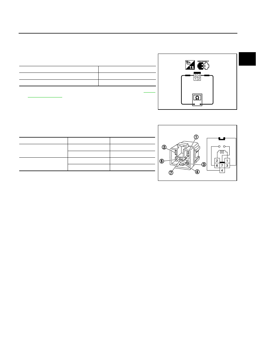
ICC BRAKE HOLD RELAY

1.

Apply 12V direct current between ICC brake hold relay terminals 1 and 2.

2.

Check continuity between relay terminals 3 and 4, 6 and 7 under
the following conditions.

3.

If NG, replace ICC brake hold relay.

Condition

Continuity

When brake pedal: Fully released.

Should not exist.

When brake pedal: Slightly depressed.

Should exist.

PBIB2103E

Condition

Between terminals

Continuity

12V direct current supply 
between terminals 1 and 2

3 and 4

Should not exist

6 and 7

Should exist

No current supply

3 and 4

Should exist

6 and 7

Should not exist

MBIB0063E

EC-604

DTC P1572 ASCD BRAKE SWITCH

DTC P1572 ASCD BRAKE SWITCH

PFP:25320

Component Description

NBS0024J

When the brake pedal is depressed, ASCD brake switch is turned
OFF and stop lamp switch is turned ON. ECM detects the state of
the brake pedal by this input of two kinds (ON/OFF signal).
Refer to 

EC-29, "AUTOMATIC SPEED CONTROL DEVICE (ASCD)"

for the ASCD function.

CONSULT-II Reference Value in Data Monitor Mode

NBS0024K

Specification data are reference values.

On Board Diagnosis Logic

NBS0024L

This self-diagnosis has the one trip detection logic.
The MIL will not light up for this diagnosis.

NOTE:

If DTC P 1572 is displayed with DTC P0605, first perform the trouble diagnosis for DTC P0605.
Refer to 

EC-489

This self-diagnosis has the one trip detection logic. When malfunction A is detected, DTC is not
stored in ECM memory. And in that case, 1st trip DTC and 1st trip freeze frame data are displayed.
1st trip DTC is erased when ignition switch OFF. And even when malfunction A is detected in two
consecutive trips, DTC is not stored in ECM memory.

PBIB2433E

MONITOR ITEM

CONDITION

SPECIFICATION

BRAKE SW1
(ASCD brake 
switch)

Ignition switch: ON

Brake pedal: Fully released

ON

Brake pedal: Slightly depressed

OFF

BRAKE SW2
(stop lamp switch)

Ignition switch: ON

Brake pedal: Fully released

OFF

Brake pedal: Slightly depressed

ON

DTC No.

Trouble diagnosis 

name

DTC detecting condition

Possible cause

P1572
1572

ASCD brake 
switch

A)

When the vehicle speed is above 30 km/h 
(19 MPH), ON signals from the stop lamp 
switch and the ASCD brake switch are 
sent to the ECM at the same time.

Harness or connectors
(The stop lamp switch circuit is shorted.)

Harness or connectors
(The ASCD brake switch circuit is shorted.)

Stop lamp switch

ASCD brake switch

Incorrect stop lamp switch installation

Incorrect ASCD brake switch installation

ECM

B)

ASCD brake switch signal is not sent to 
ECM for extremely long time while the 
vehicle is driving.

DTC P1572 ASCD BRAKE SWITCH

EC-605

C

D

E

F

G

H

I

J

K

L

M

A

EC

DTC Confirmation Procedure

NBS0024M

CAUTION:

Always drive vehicle at a safe speed.
NOTE:

If DTC Confirmation Procedure has been previously conducted, always turn ignition switch OFF and wait
at least 10 seconds before conducting the next test.

Procedure for malfunction B is not described here. It takes extremely long time to complete procedure for
malfunction B. By performing procedure for malfunction A, the incident that causes malfunction B can be
detected. 

TESTING CONDITION:
Steps 4 and 5 may be conducted with the drive wheels lifted in the shop or by driving the vehicle. If a
road test is expected to be easier, it is unnecessary to lift the vehicle.

 WITH CONSULT-II

1.

Start engine (VDC switch OFF).

2.

Select “DATA MONITOR” mode with CONSULT-II.

3.

Press MAIN switch and make sure that CRUISE lamp lights up.

4.

Drive the vehicle for at least 5 consecutive seconds under the
following conditions.

If 1st trip DTC is detected, go to 

EC-607, "Diagnostic Procedure"

.
If 1st trip DTC is not detected, go to the following step.

5.

Drive the vehicle for at least 5 consecutive seconds under the following conditions.

6.

If 1st trip DTC is detected, go to 

EC-607, "Diagnostic Procedure"

 .

 WITH GST

Follow the procedure “WITH CONSULT-II” above.

VHCL SPEED SE

More than 30 km/h (19 MPH)

Selector lever

Suitable position 

PBIB2386E

VHCL SPEED SE

More than 30 km/h (19 MPH)

Selector lever

Suitable position 

Driving location

Depress the brake pedal for more than 
five seconds so as not to come off from 
the above-mentioned vehicle speed.

EC-606

DTC P1572 ASCD BRAKE SWITCH

Wiring Diagram 

NBS0024N

TBWM1248E


Content   ..  489  490  491  492   ..