Infiniti Q45. Manual - part 486


  Index      Infiniti     Infiniti Q45 - service repair manual 2006 year


Search            copyright infringement  


Content   ..  484  485  486  487   ..


Infiniti Q45. Manual - part 486


DTC P1564 ICC STEERING SWITCH

EC-583

C

D

E

F

G

H

I

J

K

L

M

A

EC

2. 

CHECK ICC STEERING SWITCH CIRCUIT
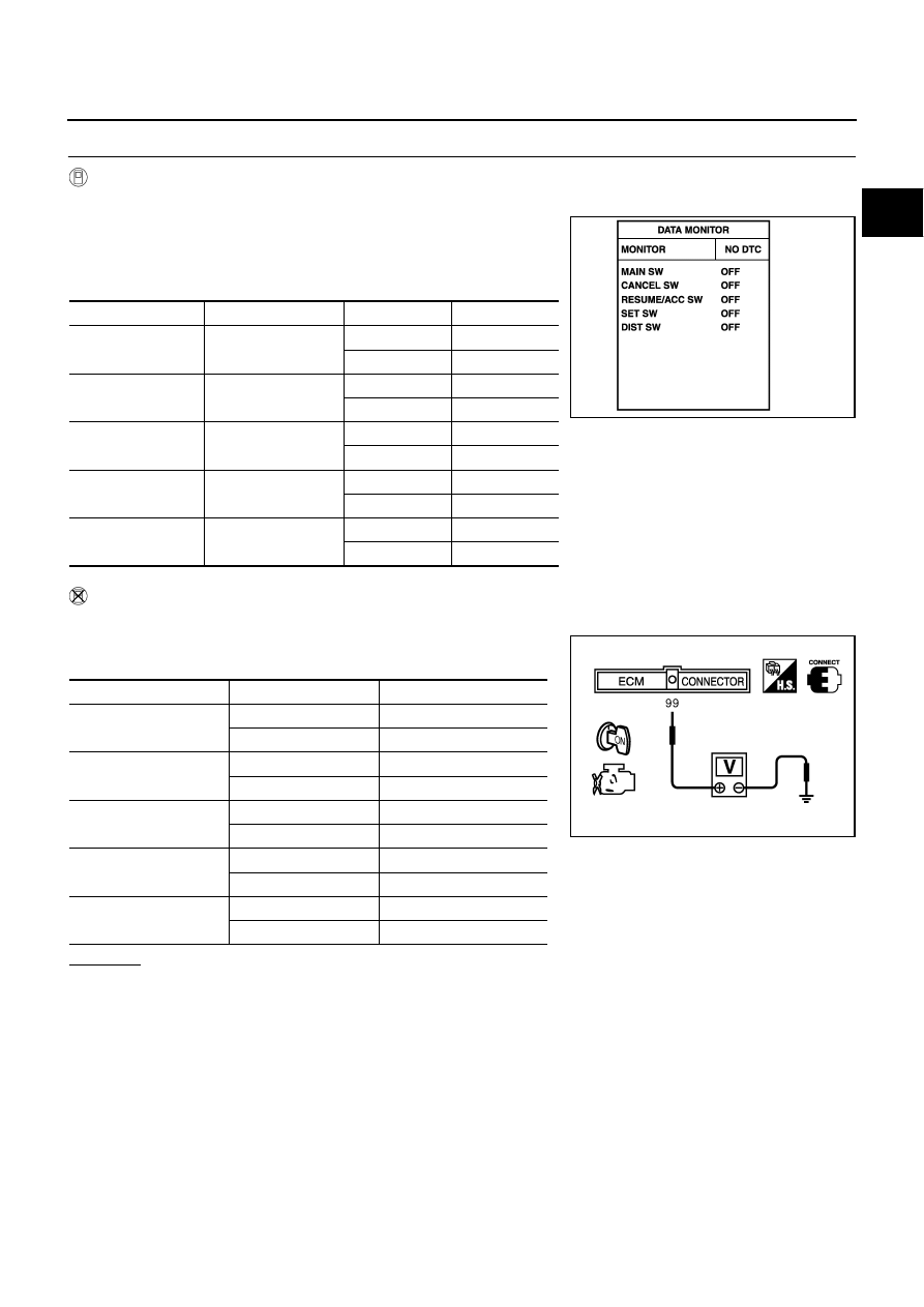
 With CONSULT-II

1.

Turn ignition switch ON.

2.

Select “MAIN SW”, “RESUME/ACC SW”, “SET SW”, “DIST SW”
and “CANCEL SW” in “DATA MONITOR” mode with CONSULT-
II.

3.

Check each item indication under the following conditions.

 Without CONSULT-II

1.

Turn ignition switch ON.

2.

Check voltage between ECM terminal 99 and ground with press-
ing each button.

OK or NG

OK

>> GO TO 8.

NG

>> GO TO 3.

Switch

Monitor item

Condition

Indication

MAIN switch

MAIN SW

Pressed

ON

Released

OFF

CANCEL switch

CANCEL SW

Pressed

ON

Released

OFF

RESUME/ACCEL-
ERATE switch

RESUME/ACC SW

Pressed

ON

Released

OFF

SET/COAST switch

SET SW

Pressed

ON

Released

OFF

DISTANCE switch

DIST SW

Pressed

ON

Released

OFF

MBIB0064E

Switch

Condition

Voltage [V]

MAIN switch

Pressed

Approx. 0

Released

Approx. 4.3

CANCEL switch

Pressed

Approx. 1.3

Released

Approx. 4.3

RESUME/ACCELER-
ATE switch

Pressed

Approx. 3.7

Released

Approx. 4.3

SET/COAST switch

Pressed

Approx. 3.0

Released

Approx. 4.3

DISTANCE switch

Pressed

Approx. 2.2

Released

Approx. 4.3

PBIB0311E

EC-584

DTC P1564 ICC STEERING SWITCH

3. 

CHECK ICC STEERING SWITCH GROUND CIRCUIT FOR OPEN AND SHORT

1.

Turn ignition switch OFF.

2.

Disconnect ECM harness connector.

3.

Disconnect ICC steering switch harness connector.

4.

Check harness continuity between ICC steering switch terminal 2 and ECM terminal 67.
Refer to Wiring Diagram.

5.

Also check harness for short to ground and short to power.

OK or NG

OK

>> GO TO 5.

NG

>> GO TO 4.

4. 

DETECT MALFUNCTIONING PART

Check the following.

Harness connectors M135, F105

Combination switch (spiral cable)

Harness for open and short between ECM and ICC steering switch

>> Repair open circuit or short to ground or short to power in harness or connectors.

5. 

CHECK ICC STEERING SWITCH INPUT SIGNAL CIRCUIT FOR OPEN AND SHORT

1.

Check harness continuity between ECM terminal 99 and ICC steering switch terminal 1.
Refer to Wiring Diagram.

2.

Also check harness for short to ground and short to power.

OK or NG

OK

>> GO TO 7.

NG

>> GO TO 6.

6. 

DETECT MALFUNCTIONING PART

Check the following.

Harness connectors M135, F105

Combination switch (spiral cable)

Harness for open and short between ECM and ICC steering switch

>> Repair open circuit or short to ground or short to power in harness or connectors.

7. 

CHECK ICC STEERING SWITCH

Refer to 

EC-585, "Component Inspection"

 .

OK or NG

OK

>> GO TO 8.

NG

>> Replace ICC steering switch.

8. 

CHECK INTERMITTENT INCIDENT

Refer to 

EC-145, "TROUBLE DIAGNOSIS FOR INTERMITTENT INCIDENT"

 .

>> INSPECTION END

Continuity should exist.

Continuity should exist.

DTC P1564 ICC STEERING SWITCH

EC-585

C

D

E

F

G

H

I

J

K

L

M

A

EC

Component Inspection

NBS00241

ICC STEERING SWITCH

1.

Disconnect ICC steering switch.

2.

Check continuity between ICC steering switch terminals 1 and 2
with pushing each switch.

If NG, replace ICC steering switch.

Switch

Condition

Resistance [

]

MAIN switch

Pressed

Approx. 0

Released

Approx. 5,500

CANCEL switch

Pressed

Approx. 310

Released

Approx. 5,500

RESUME/ACCELERATE 
switch

Pressed

Approx. 2,600

Released

Approx. 5,500

SET/COAST switch

Pressed

Approx. 1,400

Released

Approx. 5,500

DISTANCE switch

Pressed

Approx. 740

Released

Approx. 5,500

SEC008D

EC-586

DTC P1564 ASCD STEERING SWITCH

DTC P1564 ASCD STEERING SWITCH

PFP:25551

Component Description

NBS00242

ASCD steering switch has variant values of electrical resistance for each button. ECM reads voltage variation
of switch, and determines which button is operated.

Refer to 

EC-29, "AUTOMATIC SPEED CONTROL DEVICE (ASCD)"

  for the ASCD function.

CONSULT-II Reference Value in Data Monitor Mode

NBS00243

Specification data are reference values.

On Board Diagnosis Logic

NBS00244

This self-diagnosis has the one trip detection logic.
The MIL will not light up for this diagnosis
.

NOTE:
If DTC P1564 is displayed with DTC P0605, first perform the trouble diagnosis for DTC P0605. Refer to

EC-489

 .

PBIB2434E

MONITOR ITEM

CONDITION

SPECIFICATION

MAIN SW

Ignition switch: ON

MAIN switch: Pressed

ON

MAIN switch: Released

OFF

CANCEL SW

Ignition switch: ON

CANCEL switch: Pressed

ON

CANCEL switch: Released

OFF

RESUME/ACC SW

Ignition switch: ON

RESUME/ACCELERATE switch: 
Pressed

ON

RESUME/ACCELERATE switch: 
Released

OFF

SET SW

Ignition switch: ON

SET/COAST switch: Pressed

ON

SET/COAST switch: Released

OFF

DTC No.

Trouble diagnosis 

name

DTC detecting condition

Possible cause

P1564
1564

ASCD steering 
switch

An excessively high voltage signal from the ASCD 
steering switch is sent to ECM.

ECM detects that input signal from the ASCD 
steering switch is out of the specified range.

ECM detects that the ASCD steering switch is 
stuck ON.

Harness or connectors
(The switch circuit is open or shorted.)

ASCD steering switch

ECM


Content   ..  484  485  486  487   ..