Infiniti Q45. Manual - part 481


  Index      Infiniti     Infiniti Q45 - service repair manual 2006 year


Search            copyright infringement  


Content   ..  479  480  481  482   ..


Infiniti Q45. Manual - part 481


DTC P1490 VACUUM CUT VALVE BYPASS VALVE

EC-563

C

D

E

F

G

H

I

J

K

L

M

A

EC

DTC P1490 VACUUM CUT VALVE BYPASS VALVE

PFP:17372

Description

NBS0023G

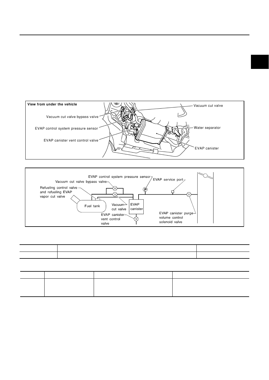
COMPONENT DESCRIPTION

The vacuum cut valve and vacuum cut valve bypass valve are installed in parallel on the EVAP purge line
between the fuel tank and the EVAP canister.
The vacuum cut valve prevents the intake manifold vacuum from being applied to the fuel tank.
The vacuum cut valve bypass valve is a solenoid type valve and generally remains closed. It opens only for on
board diagnosis.
The vacuum cut valve bypass valve responds to signals from the ECM. When the ECM sends an ON (ground)
signal, the valve is opened. The vacuum cut valve is then bypassed to apply intake manifold vacuum to the
fuel tank.

EVAPORATIVE EMISSION SYSTEM DIAGRAM

CONSULT-II Reference Value in Data Monitor Mode

NBS0023H

Specification data are reference values.

On Board Diagnosis Logic

NBS0023I

PBIB0026E

SEF323U

MONITOR ITEM

CONDITION

SPECIFICATION

VC/V BYPASS/V

Ignition switch: ON

OFF

DTC No.

Trouble diagnosis name

DTC detecting condition

Possible cause

P1490
1490

Vacuum cut valve bypass 
valve circuit

An improper voltage signal is sent to ECM 
through vacuum cut valve bypass valve.

Harness or connectors
(The valve circuit is open or shorted.)

Vacuum cut valve bypass valve

EC-564

DTC P1490 VACUUM CUT VALVE BYPASS VALVE

DTC Confirmation Procedure

NBS0023J

NOTE:
If DTC Confirmation Procedure has been previously conducted, always turn ignition switch OFF and wait at
least 10 seconds before conducting the next test.
TESTING CONDITION:
Before performing the following procedure, confirm that battery voltage is more than 11V at idle.

 WITH CONSULT-II

1.

Turn ignition switch ON.

2.

Select “DATA MONITOR” mode with CONSULT-II.

3.

Start engine and wait at least 5 seconds.

4.

If 1st trip DTC is detected, go to 

EC-566, "Diagnostic Procedure"

.

 WITH GST

Follow the procedure WITH CONSULT-II above.

SEF058Y

DTC P1490 VACUUM CUT VALVE BYPASS VALVE

EC-565

C

D

E

F

G

H

I

J

K

L

M

A

EC

Wiring Diagram

NBS0023K

TBWM1244E

EC-566

DTC P1490 VACUUM CUT VALVE BYPASS VALVE

Specification data are reference values and are measured between each terminal and ground.

CAUTION:

Do not use ECM ground terminals when measuring input/output voltage. Doing so may result in dam-
age to the ECM's transistor. Use a ground other than ECM terminals, such as the ground.

Diagnostic Procedure

NBS0023L

1. 

INSPECTION START

Do you have CONSULT-II?

Yes or No

Yes

>> GO TO 2.

No

>> GO TO 3.

2. 

CHECK VACUUM CUT VALVE BYPASS VALVE CIRCUIT

 With CONSULT-II

1.

Turn ignition switch OFF and then ON.

2.

Select “VC/V BYPASS/V” in “ACTIVE TEST” mode with CON-
SULT-II.

3.

Touch “ON/OFF” on CONSULT-II screen.

4.

Make sure that clicking sound is heard from the vacuum cut
valve bypass valve.

OK or NG

OK

>> GO TO 7.

NG

>> GO TO 3.

TER-

MINAL 

NO.

WIRE 

COLOR

ITEM

CONDITION

DATA (DC Voltage)

111

W/B

ECM relay
(Self shut-off)

[Engine is running]
[Ignition switch: OFF]

For a few seconds after turning ignition 
switch OFF

0 - 1.5V

[Ignition switch: OFF]

More than a few seconds after turning igni-
tion switch OFF

BATTERY VOLTAGE
(11 - 14V)

112

G/Y

Vacuum cut valve bypass 
valve

[Ignition switch: ON]

BATTERY VOLTAGE
(11 - 14V)

119

120

R
R

Power supply for ECM

[Ignition switch: ON]

BATTERY VOLTAGE
(11 - 14V)

PBIB3138E


Content   ..  479  480  481  482   ..