Infiniti Q45. Manual - part 479


  Index      Infiniti     Infiniti Q45 - service repair manual 2006 year


Search            copyright infringement  


Content   ..  477  478  479  480   ..


Infiniti Q45. Manual - part 479


DTC P1456 EVAP CONTROL SYSTEM

EC-555

C

D

E

F

G

H

I

J

K

L

M

A

EC

CAUTION:

Use only a genuine NISSAN fuel filler cap as a replacement. If an incorrect fuel filler cap is used,
the MIL may come on.

If the fuel filler cap is not tightened properly, the MIL may come on.

Use only a genuine NISSAN rubber tube as a replacement.

DTC Confirmation Procedure

NBS0023C

NOTE:

After repair, make sure that the hoses and clips are installed properly.

If DTC Confirmation Procedure has been previously conducted, always turn ignition switch OFF and wait
at least 10 seconds before conducting the next test.

TESTING CONDITION:

Open engine hood before conducting following procedure.

If any of following conditions are met just before the DTC confirmation procedure, leave the vehi-
cle for more than 1 hour.

Fuel filler cap is removed.

Refilled or drained the fuel.

EVAP component parts is/are removed.

Before performing the following procedure, confirm that battery voltage is more than 11V at idle.
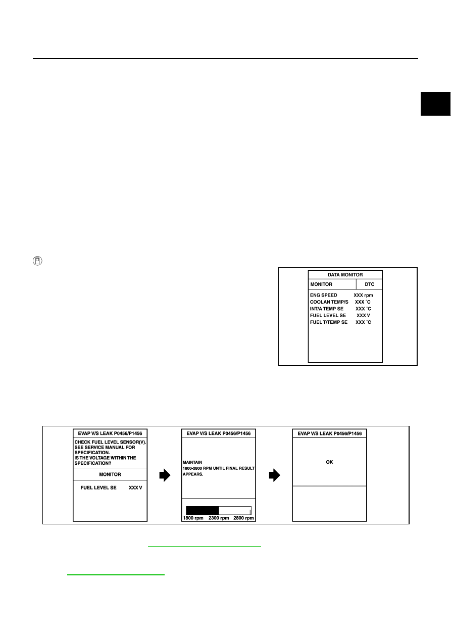
 WITH CONSULT-II

1.

Turn ignition switch ON and select “DATA MONITOR” mode with
CONSULT-II.

2.

Make sure the following conditions are met.
FUEL LEVEL SE: 0.25 - 1.15V
COOLAN TEMP/S: 0 - 32

°

C (32 - 90

°

F)

FUEL T/TMP SE: 0 - 35

°

C (32 - 95

°

F)

INT/A TEMP SE: More than 0

°

C (32

°

F)

If NG, turn ignition switch OFF and leave the vehicle in a cool
place (soak the vehicle) or refilling/draining fuel until the output
voltage condition of the “FUEL LEVEL SE” meets within the
range above and leave the vehicle for more than 1 hour. Then
start from step 1). 

3.

Turn ignition switch OFF and wait at least 10 seconds.

4.

Turn ignition switch ON.

5.

Select “EVAP V/S LEAK P0456/P1456” of “EVAPORATIVE SYSTEM” in “DTC WORK SUPPORT” mode
with CONSULT-II.
Follow the instruction displayed.

6.

Make sure that “OK” is displayed.
If “NG” is displayed, refer to 

EC-557, "Diagnostic Procedure"

 .

NOTE:

If the engine speed cannot be maintained within the range displayed on CONSULT-II screen, go
to 

EC-71, "Basic Inspection"

 .

Make sure that EVAP hoses are connected to EVAP canister purge volume control solenoid
valve properly.

PBIB2870E

PBIB0837E

EC-556

DTC P1456 EVAP CONTROL SYSTEM

Overall Function Check

NBS0023D

 WITH GST

Use this procedure to check the overall function of the EVAP very small leak function. During this check, a 1st
trip DTC might not be confirmed.

CAUTION:

Never use compressed air, doing so may damage the EVAP system.

Do not start engine.

Do not exceeded 4.12 kPa (0.042 kg/cm

2

 , 0.6 psi).

1.

Attach the EVAP service port adapter securely to the EVAP ser-
vice port.

2.

Set the pressure pump and a hose.

3.

Also set a vacuum gauge via 3-way connector and a hose.

4.

Turn ignition switch ON.

5.

Connect GST and select “Service $08”.

6.

Using “Service $08” control the EVAP canister vent control valve
(close) and vacuum cut valve bypass valve (open).

7.

Apply pressure and make sure the following conditions are sat-
isfied.
Pressure to be applied: 2.7 kPa (20 mmHg, 0.79 inHg)
Time to be waited after the pressure drawn in to the EVAP
system and the pressure to be dropped: 60 seconds and
the pressure should not be dropped more than 0.4 kPa (3 mmHg, 0.12 inHg).
If NG, go to 

EC-557, "Diagnostic Procedure"

 .

If OK, go to next step.

8.

Disconnect GST.

9.

Start engine and warm it up to normal operating temperature.

10. Turn ignition switch OFF and wait at least 10 seconds.

11. Restart engine and let it idle for 90 seconds.

12. Keep engine speed at 2,000 rpm for 30 seconds.
13. Turn ignition switch OFF.

NOTE:
For more information, refer to GST instruction manual.

PBIB3131E

SEF462UI

DTC P1456 EVAP CONTROL SYSTEM

EC-557

C

D

E

F

G

H

I

J

K

L

M

A

EC

Diagnostic Procedure

NBS0023E

1. 

CHECK FUEL FILLER CAP DESIGN

1.

Turn ignition switch OFF.

2.

Check for genuine NISSAN fuel filler cap design.

OK or NG

OK

>> GO TO 2.

NG

>> Replace with genuine NISSAN fuel filler cap.

2. 

CHECK FUEL FILLER CAP INSTALLATION

Check that the cap is tightened properly by rotating the cap clockwise.

OK or NG

OK

>> GO TO 3.

NG

>>

Open fuel filler cap, then clean cap and fuel filler neck threads using air blower.

Retighten until ratcheting sound is heard.

3. 

CHECK FUEL FILLER CAP FUNCTION

Check for air releasing sound while opening the fuel filler cap.

OK or NG

OK

>> GO TO 5.

NG

>> GO TO 4.

4. 

CHECK FUEL TANK VACUUM RELIEF VALVE

Refer to 

EC-35, "FUEL TANK VACUUM RELIEF VALVE (BUILT INTO FUEL FULLER CAP)"

 .

OK or NG

OK

>> GO TO 5.

NG

>> Replace fuel filler cap with a genuine one.

5. 

INSTALL THE PRESSURE PUMP

To locate the EVAP leak, install EVAP service port adapter and pres-
sure pump to EVAP service port securely. For the location of EVAP
service port, refer to 

EC-33, "EVAPORATIVE EMISSION LINE

DRAWING"

 .

NOTE:
Improper installation of the EVAP service port adapter to the
EVAP service port may cause leaking.

With CONSULT-II>>GO TO 6.
Without CONSULT-II>>GO TO 7.

SEF915U

SEF916U

EC-558

DTC P1456 EVAP CONTROL SYSTEM

6. 

CHECK FOR EVAP LEAK

 With CONSULT-II

1.

Turn ignition switch ON.

2.

Select “EVAP SYSTEM CLOSE” of “WORK SUPPORT” mode with CONSULT-II.

3.

Touch “START” and apply pressure into the EVAP line until the
pressure indicator reaches the middle of the bar graph.

NOTE:

Never use compressed air or a high pressure pump.

Do not exceed 4.12 kPa (0.042 kg/cm

2

 , 0.6 psi) of pres-

sure in the system.

4.

Using EVAP leak detector, locate the EVAP leak. For the leak
detector, refer to the instruction manual for more details.
Refer to 

EC-33, "EVAPORATIVE EMISSION LINE DRAWING"

 .

OK or NG

OK

>> GO TO 8.

NG

>> Repair or replace.

PEF917U

SEF200U


Content   ..  477  478  479  480   ..