Infiniti Q45. Manual - part 474


  Index      Infiniti     Infiniti Q45 - service repair manual 2006 year


Search            copyright infringement  


Content   ..  472  473  474  475   ..


Infiniti Q45. Manual - part 474


DTC P1220 FUEL PUMP CONTROL MODULE (FPCM)

EC-535

C

D

E

F

G

H

I

J

K

L

M

A

EC

DTC Confirmation Procedure

NBS00222

CAUTION:

Always drive vehicle at a safe speed.
NOTE:
If DTC Confirmation Procedure has been previously conducted, always turn ignition switch OFF and wait at
least 10 seconds before conducting the next test.
TESTING CONDITION:
Before performing the following procedure, confirm that battery voltage is more than 10V with ignition
switch ON.

 WITH CONSULT-II

1.

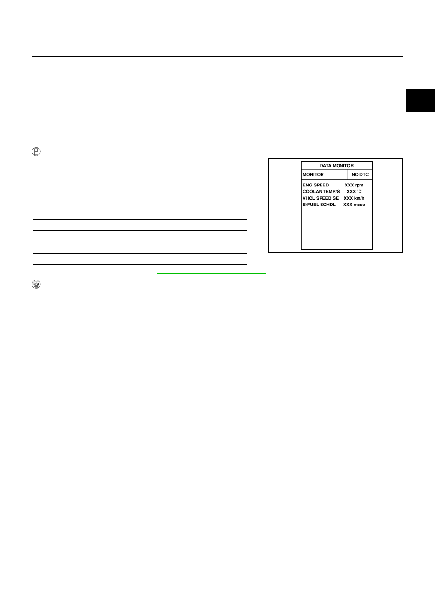
Turn ignition switch ON and select “DATA MONITOR” mode with
CONSULT-II.

2.

Make sure that “COOLAN TEMP/S” indicates less than 70

°

C

(158

°

F). If not, cool down the engine.

3.

Start engine.

4.

Hold vehicle at the following conditions for 12 seconds.

5.

If 1st trip DTC is detected, go to 

EC-537, "Diagnostic Procedure"

 .

 WITH GST

Follow the procedure WITH CONSULT-II above.

ENG SPEED

1,175 - 3,075 rpm

VHCL SPEED SE

More than 70 km/h (43 MPH)

B/FUEL SCHDL

2.0 - 31.7 msec

Selector lever

Suitable position

SEF189Y

EC-536

DTC P1220 FUEL PUMP CONTROL MODULE (FPCM)

Wiring Diagram

NBS00223

TBWM1242E

DTC P1220 FUEL PUMP CONTROL MODULE (FPCM)

EC-537

C

D

E

F

G

H

I

J

K

L

M

A

EC

Specification data are reference values and are measured between each terminal and ground.

CAUTION:

Do not use ECM ground terminals when measuring input/output voltage. Doing so may result in dam-
age to the ECM's transistor. Use a ground other than ECM terminals, such as the ground.

Diagnostic Procedure

NBS00224

1. 

CHECK GROUND CONNECTIONS

1.

Turn ignition switch OFF.

2.

Loosen and retighten three ground screws on the body.
Refer to 

EC-154, "Ground Inspection"

 .

OK or NG

OK

>> GO TO 2.

NG

>> Repair or replace ground connections.

TER-

MINAL 

NO.

WIRE 

COLOR

ITEM

CONDITION

DATA (DC Voltage)

38

G/R

Fuel pump control module 
(FPCM) check

[When cranking engine]

Approximately 0V

[Engine is running]

Warm-up condition

Idle speed

4 - 6V

39

B/R

Fuel pump control module
(FPCM)

[When cranking engine]

0 - 0.5V

[Engine is running]

Warm-up condition

Idle speed

8 - 12V

113

GY

Fuel pump relay

[Ignition switch: ON]

For 5 seconds after turning ignition switch 
ON

[Engine is running]

0 - 1.5V

[Ignition switch: ON]

More than 5 seconds after turning ignition 
switch ON

BATTERY VOLTAGE
(11 - 14V)

PBIB2417E

EC-538

DTC P1220 FUEL PUMP CONTROL MODULE (FPCM)

2. 

CHECK FPCM POWER SUPPLY CIRCUIT

1.

Disconnect fuel pump control module (FPCM) harness connector.

2.

Turn ignition switch ON.

3.

Check voltage between FPCM terminal 2 and ground with CON-
SULT-II or tester.

OK or NG

OK

>> GO TO 4.

NG

>> GO TO 3.

3. 

DETECT MALFUNCTIONING PART

Check the following.

Harness connectors M141, B211

Harness for open or short between FPCM and harness connector B211

>> Repair open circuit or short to ground or short to power in harness or connectors.

4. 

CHECK FPCM GROUND CIRCUIT-I FOR OPEN AND SHORT

1.

Turn ignition switch OFF.

2.

Check harness continuity between FPCM terminal 3 and ground.
Refer to Wiring Diagram.

3.

Also check harness for short to power.

OK or NG

OK

>> GO TO 5.

NG

>> Repair open circuit or short to power in harness or connectors.

Voltage: Battery voltage

PBIB0032E

PBIB0099E

Continuity should exist.


Content   ..  472  473  474  475   ..