Infiniti Q45. Manual - part 467


  Index      Infiniti     Infiniti Q45 - service repair manual 2006 year


Search            copyright infringement  


Content   ..  465  466  467  468   ..


Infiniti Q45. Manual - part 467


DTC P1140, P1145 IVT CONTROL POSITION SENSOR

EC-507

C

D

E

F

G

H

I

J

K

L

M

A

EC

Specification data are reference values and are measured between each terminal and ground.
Pulse signal is measured by CONSULT-II.

CAUTION:

Do not use ECM ground terminals when measuring input/output voltage. Doing so may result in dam-
age to the ECM's transistor. Use a ground other than ECM terminals, such as the ground.

: Average voltage for pulse signal (Actual pulse signal can be confirmed by oscilloscope.)

Diagnostic Procedure

NBS0020E

1. 

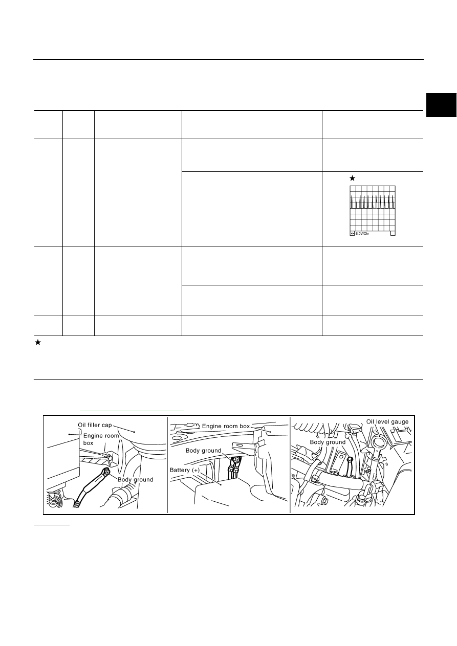
CHECK GROUND CONNECTIONS

1.

Turn ignition switch OFF.

2.

Loosen and retighten three ground screws on the body.
Refer to 

EC-154, "Ground Inspection"

 .

OK or NG

OK

>> GO TO 2.

NG

>> Repair or replace ground connections.

TER-

MINAL 

NO.

WIRE 

COLOR

ITEM

CONDITION

DATA (DC Voltage)

53

W

Intake valve timing control 
position sensor (bank 2)

[Engine is running]

Warm-up condition

Idle speed

0 - 1.0V

[Engine is running]

Engine speed: 2,000 rpm

0 - 1.0V

111

W/B

ECM relay
(Self shut-off)

[Engine is running]
[Ignition switch: OFF]

For a few seconds after turning ignition 
switch OFF

0 - 1.5V

[Ignition switch: OFF]

More than a few seconds after turning igni-
tion switch OFF

BATTERY VOLTAGE
(11 - 14V)

119

120

R
R

Power supply for ECM

[Ignition switch: ON]

BATTERY VOLTAGE
(11 - 14V)

PBIB2046E

PBIB2417E

EC-508

DTC P1140, P1145 IVT CONTROL POSITION SENSOR

2. 

CHECK INTAKE VALVE TIMING CONTROL POSITION SENSOR POWER SUPPLY CIRCUIT

1.

Disconnect intake valve timing control position sensor harness connector.

2.

Turn ignition switch ON.

3.

Check voltage between intake valve timing control position sen-
sor terminal 3 and ground with CONSULT-II or tester.

OK or NG

OK

>> GO TO 4.

NG

>> GO TO 3.

3. 

DETECT MALFUNCTIONING PART

Check the following.

Harness connectors M135, F105

Harness for open or short between intake valve timing control position sensor and ECM relay

Harness for open or short between intake valve timing control position sensor and ECM

>> Repair open circuit or short to ground or short to power in harness or connectors.

4. 

CHECK INTAKE VALVE TIMING CONTROL POSITION SENSOR GROUND CIRCUIT FOR OPEN AND 

SHORT

1.

Turn ignition switch OFF.

2.

Check harness continuity between intake valve timing control position sensor terminal 1 and ground.
Refer to Wiring Diagram.

3.

Also check harness for short to power. 

OK or NG

OK

>> GO TO 6.

NG

>> GO TO 5.

5. 

DETECT MALFUNCTIONING PART

Check the following.

Harness connectors F32, E32

Harness for open or short between intake valve timing control position sensor and ground

>> Repair open circuit or short to power in harness or connectors.

Voltage: Battery voltage

PBIB2422E

SEF509Y

Continuity should exist.

DTC P1140, P1145 IVT CONTROL POSITION SENSOR

EC-509

C

D

E

F

G

H

I

J

K

L

M

A

EC

6. 

CHECK INTAKE VALVE TIMING CONTROL POSITION SENSOR INPUT SIGNAL CIRCUIT FOR OPEN 

AND SHORT

1.

Disconnect ECM harness connector.

2.

Check harness continuity between the following;
ECM terminal 72 and intake valve timing control position sensor (bank 1) terminal 2 or 
ECM terminal 53 and intake valve timing control position sensor (bank 2) terminal 2.
Refer to Wiring Diagram.

3.

Also check harness for short to ground and short to power. 

OK or NG

OK

>> GO TO 7.

NG

>> Repair open circuit or short to ground or short to power in harness or connectors.

7. 

CHECK INTAKE VALVE TIMING CONTROL POSITION SENSOR

Refer to 

EC-510, "Component Inspection"

 .

OK or NG

OK

>> GO TO 8.

NG

>> Replace intake valve timing control position sensor.

8. 

CHECK CRANKSHAFT POSITION SENSOR (POS)

Refer to 

EC-378, "Component Inspection"

 .

OK or NG

OK

>> GO TO 9.

NG

>> Replace crankshaft position sensor (POS).

9. 

CHECK CAMSHAFT POSITION SENSOR (PHASE)

Refer to 

EC-385, "Component Inspection"

 .

OK or NG

OK

>> GO TO 10.

NG

>> Replace camshaft position sensor (PHASE).

10. 

CHECK CAMSHAFT SPROCKET

Check accumulation of debris to the signal pick-up portion of the camshaft sprocket. Refer to 

EM-39, "TIMING

CHAIN"

 .

OK or NG

OK

>> GO TO 11.

NG

>> Remove debris and clean the signal pick-up cutout of camshaft sprocket.

11. 

CHECK INTERMITTENT INCIDENT

Refer to 

EC-145, "TROUBLE DIAGNOSIS FOR INTERMITTENT INCIDENT"

 .

>> INSPECTION END

Continuity should exist.

EC-510

DTC P1140, P1145 IVT CONTROL POSITION SENSOR

Component Inspection

NBS0020F

INTAKE VALVE TIMING CONTROL POSITION SENSOR

1.

Disconnect intake valve timing control position sensor harness connector.

2.

Loosen the fixing bolt of the sensor.

3.

Remove the sensor.

4.

Visually check the sensor for chipping.

5.

Check resistance as shown below.

6.

If NG, replace intake valve timing control position sensor.

Removal and Installation

NBS0020G

INTAKE VALVE TIMING CONTROL POSITION SENSOR

Refer to 

EM-39, "TIMING CHAIN"

 .

SEF362Z

Terminal No. (Polarity)

Resistance 

 [at 25

°

C (77

°

F)]

3 (+) - 1 (-)

Except 0 or 

2 (+) - 1 (-)

3 (+) - 2 (-)

PBIB0194E


Content   ..  465  466  467  468   ..