Infiniti Q45. Manual - part 450


  Index      Infiniti     Infiniti Q45 - service repair manual 2006 year


Search            copyright infringement  


Content   ..  448  449  450  451   ..


Infiniti Q45. Manual - part 450


DTC P0452 EVAP CONTROL SYSTEM PRESSURE SENSOR

EC-439

C

D

E

F

G

H

I

J

K

L

M

A

EC

Specification data are reference values and are measured between each terminal and ground.

CAUTION:

Do not use ECM ground terminals when measuring input/output voltage. Doing so may result in dam-
age to the ECM's transistor. Use a ground other than ECM terminals, such as the ground.

Diagnostic Procedure

NBS001XM

1. 

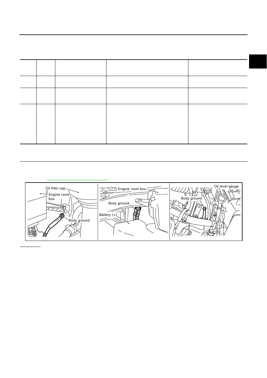
CHECK GROUND CONNECTIONS

1.

Turn ignition switch OFF.

2.

Loosen and retighten three ground screws on the body.
Refer to 

EC-154, "Ground Inspection"

 .

OK or NG

OK

>> GO TO 2.

NG

>> Repair or replace ground connections.

TER-

MINAL 

NO.

WIRE 

COLOR

ITEM

CONDITION

DATA (DC Voltage)

32

G

EVAP control system pres-
sure sensor

[Ignition switch: ON]

Approximately 1.8 - 4.8V

48

R

Sensor power supply
(EVAP control system pres-
sure sensor)

[Ignition switch: ON]

Approximately 5V

67

B

Sensor ground
(MAF sensor, IAT sensor, 
ECT sensor, FTT sensor, 
EVAP control system pres-
sure sensor, PSP sensor, 
ICC steering switch, ASCD 
steering switch, Refrigerant 
pressure sensor)

[Engine is running]

Warm-up condition

Idle speed

Approximately 0V

PBIB2417E

EC-440

DTC P0452 EVAP CONTROL SYSTEM PRESSURE SENSOR

2. 

CHECK CONNECTOR

1.

Disconnect EVAP control system pressure sensor harness connector.

2.

Check sensor harness connector for water.

OK or NG

OK

>> GO TO 3.

NG

>> Repair or replace harness connector.

3. 

CHECK EVAP CONTROL SYSTEM PRESSURE SENSOR POWER SUPPLY CIRCUIT

1.

Turn ignition switch ON.

2.

Check voltage between EVAP control system pressure sensor
terminal 1 and ground with CONSULT-II or tester.

OK or NG

OK

>> GO TO 5.

NG

>> GO TO 4.

4. 

DETECT MALFUNCTIONING PART

Check the following.

Harness connectors B401, B251

Harness connectors B211, M141

Harness connectors M135, F105

Harness for open or short between EVAP control system pressure sensor and ECM

>> Repair open circuit or short to ground or short to power in harness or connectors.

Water should not exist.

PBIB0026E

Voltage: Approximately 5V

PBIB0155E

DTC P0452 EVAP CONTROL SYSTEM PRESSURE SENSOR

EC-441

C

D

E

F

G

H

I

J

K

L

M

A

EC

5. 

CHECK EVAP CONTROL SYSTEM PRESSURE SENSOR GROUND CIRCUIT FOR OPEN AND 

SHORT

1.

Turn ignition switch OFF.

2.

Disconnect ECM harness connector.

3.

Check harness continuity between EVAP control system pressure sensor terminal 3 and ECM terminal
67.
Refer to Wiring Diagram.

4.

Also check harness for short to ground and short to power.

OK or NG

OK

>> GO TO 7.

NG

>> GO TO 6.

6. 

DETECT MALFUNCTIONING PART

Check the following.

Harness connectors B401, B251

Harness connectors B211, M141

Harness connectors M135, F105

Harness for open or short between EVAP control system pressure sensor and ECM

>> Repair open circuit or short to ground or short to power in harness or connectors.

7. 

CHECK EVAP CONTROL SYSTEM PRESSURE SENSOR INPUT SIGNAL CIRCUIT FOR OPEN AND 

SHORT

1.

Check harness continuity between ECM terminal 32 and EVAP control system pressure sensor terminal
2.
Refer to Wiring Diagram.

2.

Also check harness for short to ground and short to power.

OK or NG

OK

>> GO TO 9.

NG

>> GO TO 8.

8. 

DETECT MALFUNCTIONING PART

Check the following.

Harness connectors B401, B251

Harness connectors B211, M141

Harness connectors M135, F105

Harness for open or short between EVAP control system pressure sensor and ECM

>> Repair open circuit or short to ground or short to power in harness or connectors.

9. 

CHECK EVAP CONTROL SYSTEM PRESSURE SENSOR

Refer to 

EC-442, "Component Inspection"

 .

OK or NG

OK

>> GO TO 10.

NG

>> Replace EVAP control system pressure sensor.

Continuity should exist.

Continuity should exist.

EC-442

DTC P0452 EVAP CONTROL SYSTEM PRESSURE SENSOR

10. 

CHECK INTERMITTENT INCIDENT

Refer to 

EC-145, "TROUBLE DIAGNOSIS FOR INTERMITTENT INCIDENT"

 .

>> INSPECTION END

Component Inspection

NBS001XN

EVAP CONTROL SYSTEM PRESSURE SENSOR

1.

Remove EVAP control system pressure sensor with its harness connector connected.

2.

Remove hose from EVAP control system pressure sensor.

3.

Install a vacuum pump to EVAP control system pressure sensor.

4.

Turn ignition switch ON.

5.

Use pump to apply vacuum and pressure to EVAP control sys-
tem pressure sensor as shown in figure.

CAUTION:

Always calibrate the vacuum pump gauge when using it.

Do not apply below -93.3 kPa (-700 mmHg, -27.56 inHg) or
pressure over 101.3 kPa (760 mmHg, 29.92 inHg).

6.

Check voltage between ECM terminal 32 and ground with CON-
SULT-II or tester.

CAUTION:

Discard any EVAP control system pressure sensor which has dropped from a height of more than
0.5 m (19.7 in) onto a hard surface such a concrete floor; use a new one.

7.

If NG, replace EVAP control system pressure sensor.

Applied vacuum kPa

(mmHg, inHg)

Voltage V

Not applied

1.8 - 4.8

-26.7 (-200 mmHg, -7.87)

2.1 to 2.5V lower than above value

PBIB1173E


Content   ..  448  449  450  451   ..