Infiniti Q45. Manual - part 441
DTC P0442 EVAP CONTROL SYSTEM
EC-403
C
D
E
F
G
H
I
J
K
L
M
A
EC
21.
CHECK REFUELING EVAP VAPOR LINE
Check refuelling EVAP vapor line between EVAP canister and fuel tank for clogging, kink, looseness and
improper connection. For location, refer to
EC-38, "ON BOARD REFUELING VAPOR RECOVERY (ORVR)"
OK or NG
OK
>> GO TO 22.
NG
>> Repair or replace hoses and tubes.
22.
CHECK SIGNAL LINE AND RECIRCULATION LINE
Check signal line and recirculation line between filler neck tube and fuel tank for clogging, kink, cracks, loose-
ness and improper connection.
OK or NG
OK
>> GO TO 23.
NG
>> Repair or replace hose, tube or filler neck tube.
23.
CHECK REFUELING CONTROL VALVE
Refer to
OK or NG
OK
>> GO TO 24.
NG
>> Replace refueling EVAP vapor cut valve with fuel tank.
24.
CHECK FUEL LEVEL SENSOR
Refer to
DI-22, "CHECK FUEL LEVEL SENSOR UNIT"
.
OK or NG
OK
>> GO TO 25.
NG
>> Replace fuel level sensor unit.
25.
CHECK INTERMITTENT INCIDENT
Refer to
EC-145, "TROUBLE DIAGNOSIS FOR INTERMITTENT INCIDENT"
>> INSPECTION END
Component Inspection
NBS001X1
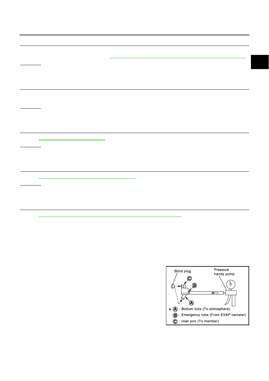
WATER SEPARATOR
1.
Check visually for insect nests in the water separator air inlet.
2.
Check visually for cracks or flaws in the appearance.
3.
Check visually for cracks or flaws in the hose.
4.
Check that A and C are not clogged by blowing air into B with
A , and then C plugged.
5.
In case of NG in items 2 - 4, replace the parts.
NOTE:
●
Do not disassemble water separator.
PBIB1032E