Infiniti Q45. Manual - part 427
DTC P0182, P0183 FTT SENSOR
EC-347
C
D
E
F
G
H
I
J
K
L
M
A
EC
4.
CHECK FUEL TANK TEMPERATURE SENSOR GROUND CIRCUIT FOR OPEN AND SHORT
1.
Turn ignition switch OFF.
2.
Disconnect ECM harness connector.
3.
Check harness continuity between “fuel level sensor unit and fuel pump” terminal 2 and ECM terminal 67.
Refer to Wiring Diagram.
4.
Also check harness for short to ground and short to power.
OK or NG
OK
>> GO TO 6.
NG
>> GO TO 5.
5.
DETECT MALFUNCTIONING PART
Check the following.
●
Harness connectors B211, M141
●
Harness connectors M135, F105
●
Harness for open or short between ECM and “fuel level sensor unit and fuel pump”
>> Repair open circuit or short to ground or short to power in harness or connector.
6.
CHECK FUEL TANK TEMPERATURE SENSOR
Refer to
EC-346, "Diagnostic Procedure"
OK or NG
OK
>> GO TO 7.
NG
>> Replace fuel level sensor unit.
7.
CHECK INTERMITTENT INCIDENT
Refer to
EC-145, "TROUBLE DIAGNOSIS FOR INTERMITTENT INCIDENT"
>> INSPECTION END
Component Inspection
NBS001VQ
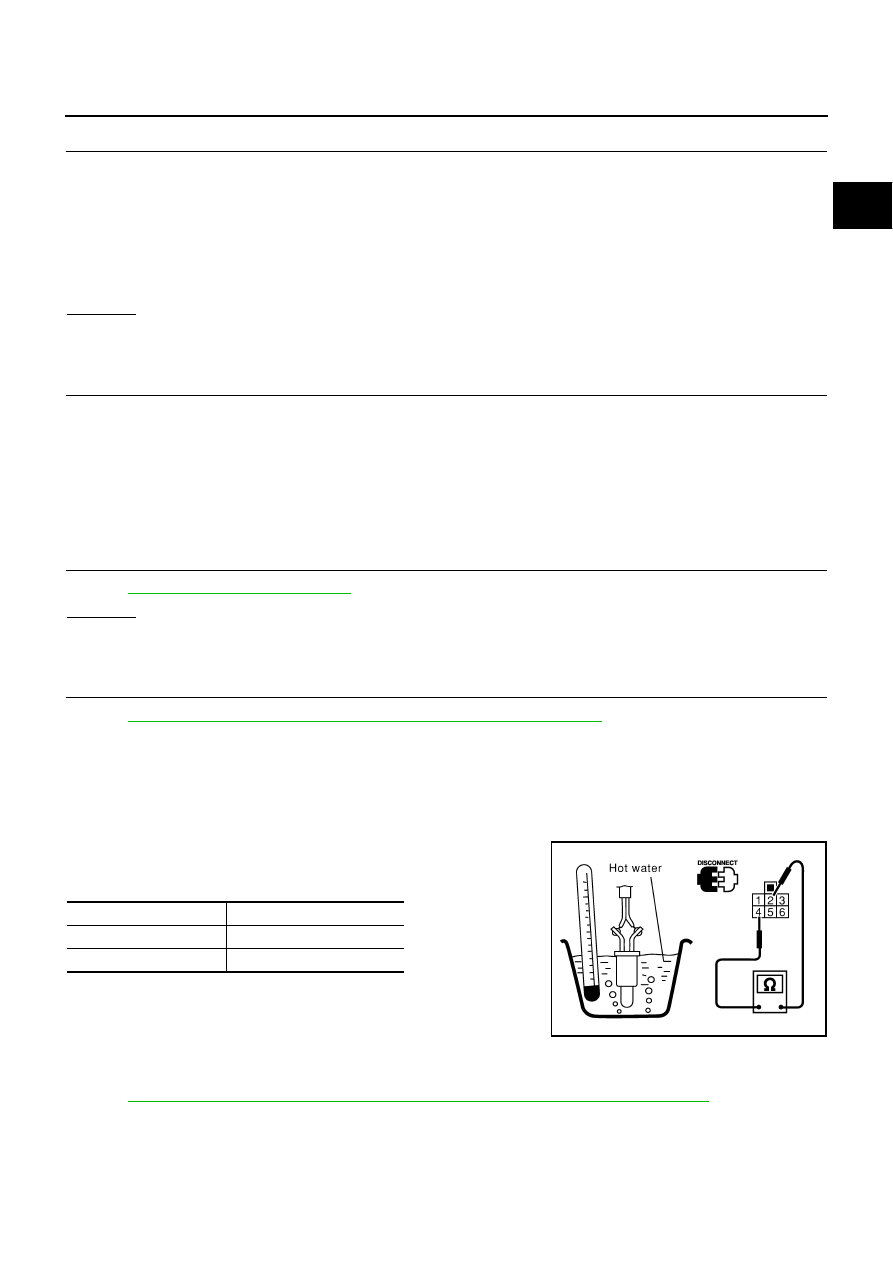
FUEL TANK TEMPERATURE SENSOR
1.
Remove fuel level sensor unit.
2.
Check resistance between “fuel level sensor unit and fuel pump”
terminals 4 and 2 by heating with hot water or heat gun as
shown in the figure.
Removal and Installation
NBS001VR
FUEL TANK TEMPERATURE SENSOR
Refer to
FL-3, "FUEL LEVEL SENSOR UNIT, FUEL FILTER AND FUEL PUMP ASSEMBLY"
Continuity should exist.
Temperature
°
C (
°
F)
Resistance k
Ω
20 (68)
2.3 - 2.7
50 (122)
0.79 - 0.90
PBIB0200E