Infiniti Q45. Manual - part 414
DTC P0138, P0158 HO2S2
EC-295
C
D
E
F
G
H
I
J
K
L
M
A
EC
Specification data are reference values and are measured between each terminal and ground.
CAUTION:
Do not use ECM ground terminals when measuring input/output voltage. Doing so may result in dam-
age to the ECM's transistor. Use a ground other than ECM terminals, such as the ground.
Diagnostic Procedure
NBS001UU
PROCEDURE FOR MALFUNCTION A
1.
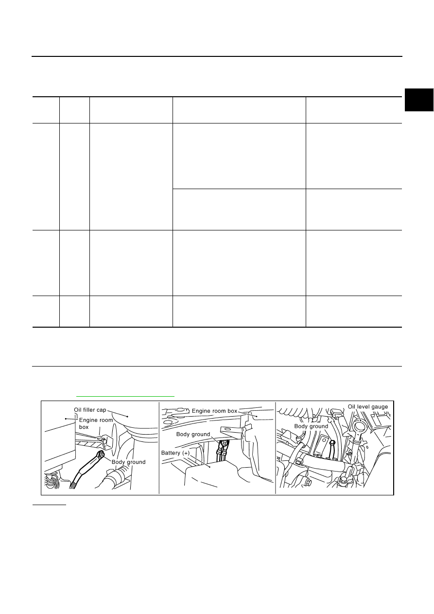
CHECK GROUND CONNECTIONS
1.
Turn ignition switch OFF.
2.
Loosen and retighten three ground screws on the body.
Refer to
OK or NG
OK
>> GO TO 2.
NG
>> Repair or replace ground connections.
TER-
MINAL
NO.
WIRE
COLOR
ITEM
CONDITION
DATA (DC Voltage)
25
G
Heated oxygen sensor 2
heater (bank 2)
[Engine is running]
●
Engine speed: Below 3,600 rpm after the
following conditions are met
–
Engine: After warming up
–
Keeping the engine speed between 3,500
and 4,000 rpm for 1 minute and at idle for 1
minute under no load
0 - 1.0V
[Ignition switch: ON]
●
Engine stopped
[Engine is running]
●
Engine speed: Above 3,600 rpm
BATTERY VOLTAGE
(11 - 14V)
74
B
Heated oxygen sensor 2
(bank 2)
[Engine is running]
●
Revving engine from idle to 3,000 rpm
quickly after the following conditions are met
–
Engine: After warming up
–
After keeping the engine speed between
3,500 and 4,000 rpm for 1 minute and at idle
for 1 minute under no load
0 - Approximately 1.0V
78
OR
Sensor ground
(Heated oxygen sensor 2)
[Engine is running]
●
Warm-up condition
●
Idle speed
Approximately 0V
PBIB2417E