Index Infiniti Infiniti Q45 - service repair manual 2006 year
Search copyright infringement
Content .. 403 404 405 406 ..
Infiniti Q45. Manual - part 405
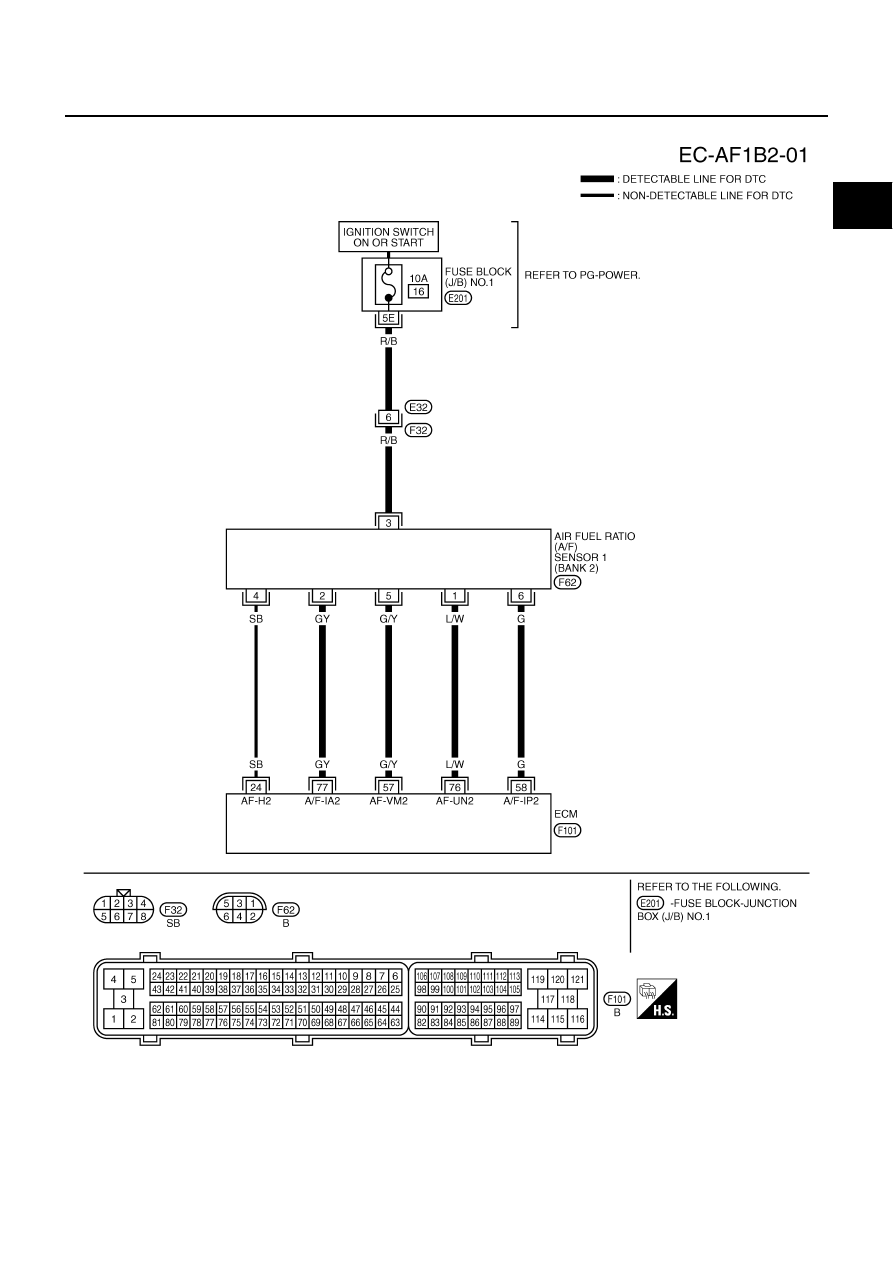
DTC P0132, P0152 A/F SENSOR 1
EC-259
C
D
E
F
G
H
I
J
K
L
M
A
EC
BANK 2
TBWM1225E