Index Infiniti Infiniti Q45 - service repair manual 2006 year
Search copyright infringement
Content .. 394 395 396 397 ..
Infiniti Q45. Manual - part 396
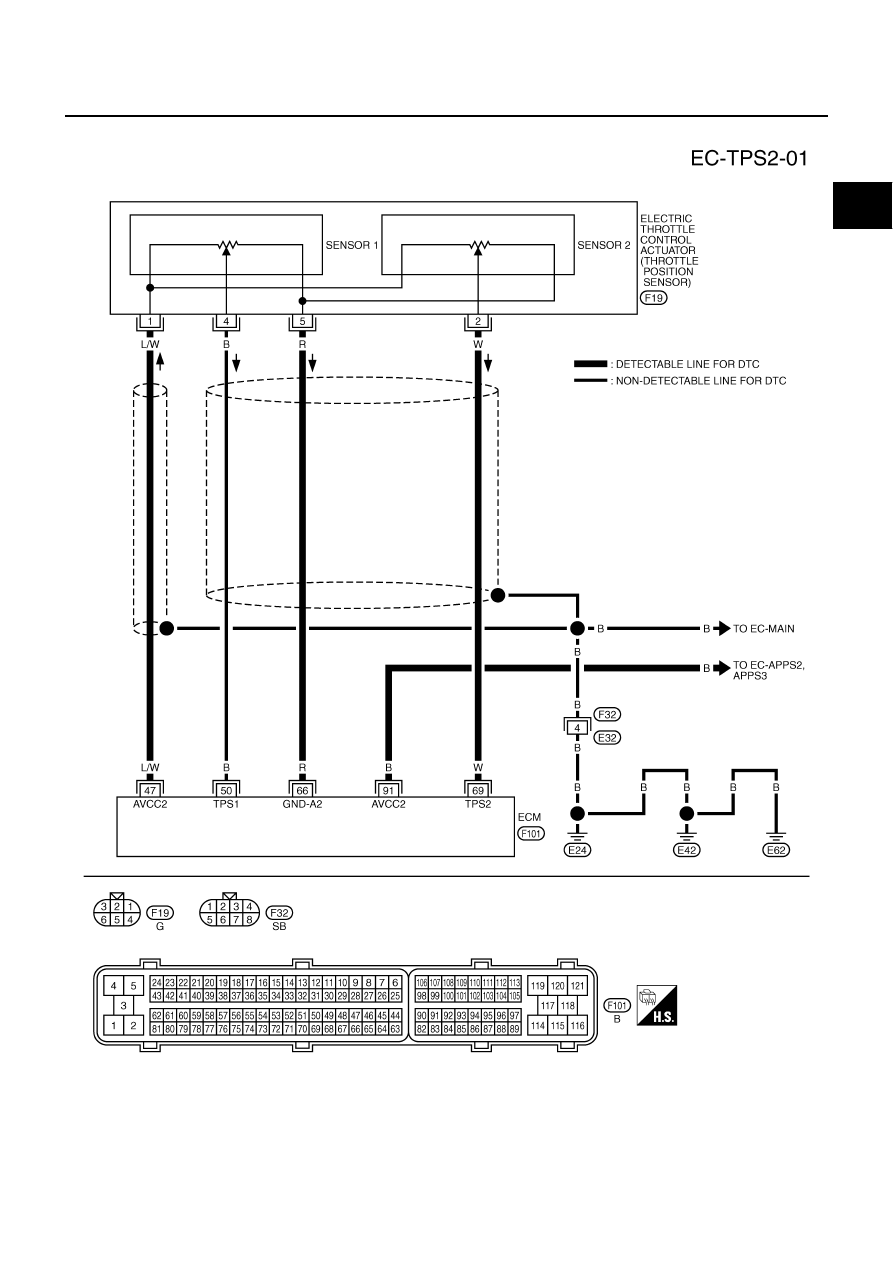
DTC P0122, P0123 TP SENSOR
EC-223
C
D
E
F
G
H
I
J
K
L
M
A
EC
Wiring Diagram
NBS001TE
TBWM0540E