Infiniti Q45. Manual - part 385
DTC P0031, P0032, P0051, P0052 A/F SENSOR 1 HEATER
EC-179
C
D
E
F
G
H
I
J
K
L
M
A
EC
5.
CHECK A/F SENSOR 1 HEATER
Refer to
EC-179, "Component Inspection"
OK or NG
OK
>> GO TO 6.
NG
>> Replace malfunctioning air fuel ratio sensor 1.
6.
CHECK INTERMITTENT INCIDENT
Refer to
EC-145, "TROUBLE DIAGNOSIS FOR INTERMITTENT INCIDENT"
>> INSPECTION END
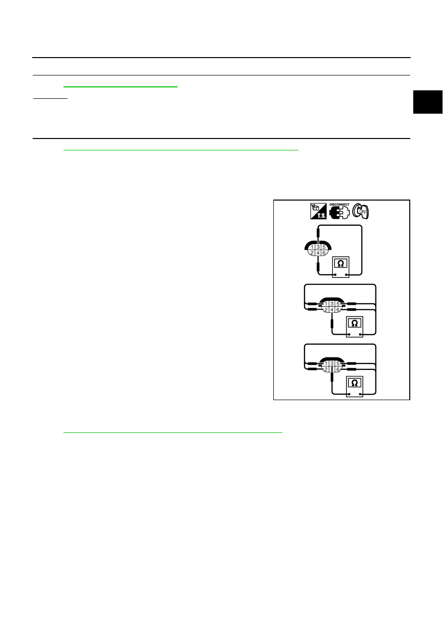
Component Inspection
NBS002WW
AIR FUEL RATIO (A/F) SENSOR 1 HEATER
Check resistance between terminals 3 and 4.
Check continuity between terminals 3 and 1, 2, 5, 6, terminals 4 and
1, 2, 5, 6.
If NG, replace the A/F sensor 1.
CAUTION:
●
Discard any A/F sensor which has been dropped from a
height of more than 0.5 m (19.7 in) onto a hard surface such
as a concrete floor; use a new one.
●
Before installing new A/F sensor, clean exhaust system
threads using Heated Oxygen Sensor Thread Cleaner tool
J-43897-18 or J-43897-12 and approved anti-seize lubricant.
Removal and Installation
NBS002WX
AIR FUEL RATIO (A/F) SENSOR 1
Refer to
EM-23, "EXHAUST MANIFOLD AND THREE WAY CATALYST"
Resistance: 2.3 - 4.3
Ω
[at 25
°
C (77
°
F)]
Continuity should not exist.
PBIB1684E