Infiniti Q45. Manual - part 381
DTC P0011, P0021 IVT CONTROL
EC-163
C
D
E
F
G
H
I
J
K
L
M
A
EC
DTC Confirmation Procedure
NBS001RU
CAUTION:
Always drive at a safe speed.
NOTE:
If DTC Confirmation Procedure has been previously conducted, always turn ignition switch OFF and wait at
least 10 seconds before conducting the next test.
TESTING CONDITION:
Before performing the following procedure, confirm that battery voltage is between 10V and 16V at
idle.
PROCEDURE FOR MALFUNCTION A
With CONSULT-II
1.
Turn ignition switch ON.
2.
Select “DATA MONITOR” mode with CONSULT-II.
3.
Maintain the following conditions for at least 10 consecutive sec-
onds.
4.
Maintain the following conditions for at least 20 consecutive sec-
onds.
5.
If the 1st trip DTC is detected, go to
EC-167, "Diagnostic Procedure"
With GST
Follow the procedure With CONSULT-II above.
PROCEDURE FOR MALFUNCTION B
With CONSULT-II
1.
Turn ignition switch ON.
2.
Select “DATA MONITOR” mode with CONSULT-II.
3.
Maintain the following conditions for at least 10 consecutive sec-
onds.
4.
If the 1st trip DTC is detected, go to
.
With GST
Follow the procedure With CONSULT-II above.
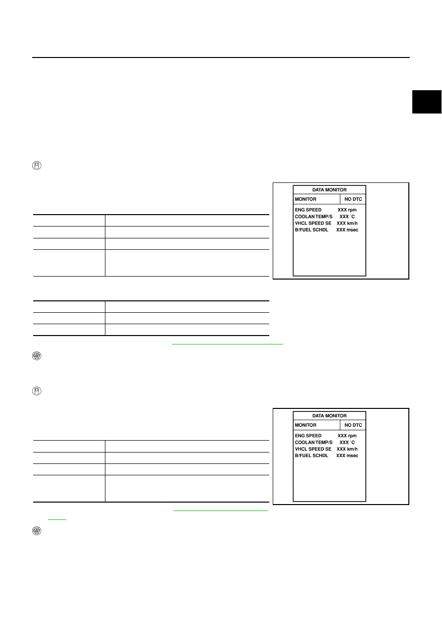
ENG SPEED
More than 2,000 rpm (A constant rotation is maintained.)
COOLAN TEMP/S
More than 70
°
C (158
°
F)
Selector lever
1st or 2nd position
Driving location uphill
Driving vehicle uphill
(Increased engine load will help maintain the driving con-
ditions required for this test.)
ENG SPEED
Idle
COOLAN TEMP/S
More than 70
°
C (158
°
F)
Selector lever
P or N position
PBIB0164E
ENG SPEED
1,700 - 3,175 rpm (A constant rotation is maintained.)
COOLAN TEMP/S
70 - 105
°
C (158 - 221
°
F)
Selector lever
1st or 2nd position
Driving location uphill
Driving vehicle uphill
(Increased engine load will help maintain the driving con-
ditions required for this test.)
PBIB0164E