Infiniti Q45. Manual - part 349


  Index      Infiniti     Infiniti Q45 - service repair manual 2006 year


Search            copyright infringement  


Content   ..  347  348  349  350   ..


Infiniti Q45. Manual - part 349


EVAPORATIVE EMISSION SYSTEM

EC-35

C

D

E

F

G

H

I

J

K

L

M

A

EC

Component Inspection

NBS001QE

EVAP CANISTER

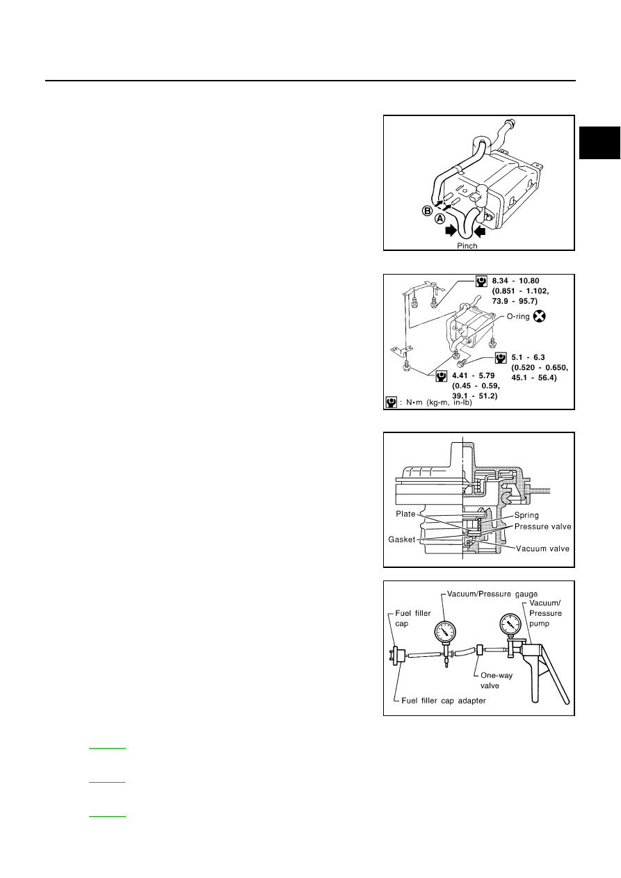
Check EVAP canister as follows:

1.

Pinch the fresh air hose.

2.

Blow air into port A  and check that it flows freely out of port B .

Tightening Torque

Tighten EVAP canister as shown in the figure.
Make sure new O-ring is installed properly between EVAP can-
ister and EVAP canister vent control valve.

FUEL TANK VACUUM RELIEF VALVE (BUILT INTO FUEL FULLER CAP)

1.

Wipe clean valve housing.

2.

Check valve opening pressure and vacuum.

3.

If out of specification, replace fuel filler cap as an assembly.

CAUTION:

Use only a genuine fuel filler cap as a replacement. If an incor-
rect fuel filler cap is used, the MIL may come on.

VACUUM CUT VALVE AND VACUUM CUT VALVE BYPASS VALVE

Refer to 

EC-568

 .

EVAP CANISTER PURGE VOLUME CONTROL SOLENOID VALVE

Refer to 

EC-411

 .

FUEL TANK TEMPERATURE SENSOR

Refer to 

EC-343

 .

SEF396T

SEF397T

SEF445Y

Pressure:

15.3 - 20.0 kPa (0.156 - 0.204 kg/cm

2

 , 2.22 - 

2.90 psi)

Vacuum:

6.0 to 

3.3 kPa (

0.061 to 

0.034 kg/cm

2

 , 

0.87 to 

0.48 psi)

SEF943S

EC-36

EVAPORATIVE EMISSION SYSTEM

EVAP SERVICE PORT

Positive pressure is delivered to the EVAP system through the EVAP
service port. If fuel vapor leakage in the EVAP system occurs, use a
leak detector to locate the leak.

How to Detect Fuel Vapor Leakage

NBS001QF

CAUTION:

Never use compressed air or a high pressure pump.

Do not exceed 4.12 kPa (0.042 kg/cm

2

 , 0.6 psi) of pressure in EVAP system.

NOTE:

Do not start engine.

Improper installation of EVAP service port adapter to the EVAP service port may cause a leak.

 WITH CONSULT-II

1.

Attach the EVAP service port adapter securely to the EVAP service port.

2.

Also attach the pressure pump and hose to the EVAP service port adapter.

3.

Turn ignition switch ON.

4.

Select the “EVAP SYSTEM CLOSE” of “WORK SUPPORT
MODE” with CONSULT-II.

5.

Touch “START”. A bar graph (Pressure indicating display) will
appear on the screen.

6.

Apply positive pressure to the EVAP system until the pressure
indicator reaches the middle of the bar graph.

7.

Remove EVAP service port adapter and hose with pressure
pump.

SEF462UA

PEF838U

PEF917U

EVAPORATIVE EMISSION SYSTEM

EC-37

C

D

E

F

G

H

I

J

K

L

M

A

EC

8.

Locate the leak using a leak detector. Refer to 

EC-33, "EVAPO-

RATIVE EMISSION LINE DRAWING"

 .

 WITHOUT CONSULT-II

1.

Attach the EVAP service port adapter securely to the EVAP ser-
vice port.

2.

Also attach the pressure pump with pressure gauge to the EVAP
service port adapter.

3.

Apply battery voltage to between the terminals of both EVAP canister vent control valve and vacuum cut
valve bypass valve to make a closed EVAP system.

4.

To locate the leak, deliver positive pressure to the EVAP system until pressure gauge points reach 1.38 to
2.76 kPa (0.014 to 0.028 kg/cm

2

 , 0.2 to 0.4 psi).

5.

Remove EVAP service port adapter and hose with pressure pump.

6.

Locate the leak using a leak detector. Refer to 

EC-33, "EVAPORATIVE EMISSION LINE DRAWING"

 .

SEF200U

SEF462UA

PBIB0026E

EC-38

ON BOARD REFUELING VAPOR RECOVERY (ORVR)

ON BOARD REFUELING VAPOR RECOVERY (ORVR)

PFP:00032

System Description

NBS001QG

From the beginning of refueling, the fuel tank pressure goes up. When the pressure reaches the setting value
of the refueling control valve (RCV) opening pressure, the RCV is opened. After RCV opens, the air and vapor
inside the fuel tank go through refueling EVAP vapor cut valve, RCV and refueling vapor line to the EVAP can-
ister. The vapor is absorbed by the EVAP canister and the air is released to the atmosphere.
When the refueling has reached the full level of the fuel tank, the refueling EVAP vapor cut valve is closed and
refueling is stopped because of auto shut-off. The vapor which was absorbed by the EVAP canister is purged
during driving.
The RCV is always closed during driving and the evaporative emission control system is operated the same
as conventional system.

WARNING:

When conducting inspections below, be sure to observe the following:

Put a “CAUTION: INFLAMMABLE” sign in workshop.

Do not smoke while servicing fuel system. Keep open flames and sparks away from work area.

Be sure to furnish the workshop with a CO

2

  fire extinguisher.

CAUTION:

Before removing fuel line parts, carry out the following procedures:

Put drained fuel in an explosion-proof container and put lid on securely.

Release fuel pressure from fuel line. Refer to 

EC-80, "FUEL PRESSURE RELEASE"

 .

Disconnect battery ground cable.

Always replace O-ring when the fuel gauge retainer is removed.

Do not kink or twist hose and tube when they are installed.

Do not tighten hose and clamps excessively to avoid damaging hoses.

After installation, run engine and check for fuel leaks at connection.

Do not attempt to top off the fuel tank after the fuel pump nozzle shuts off automatically.
Continued refueling may cause fuel overflow, resulting in fuel spray and possibly a fire.

SEF206VA


Content   ..  347  348  349  350   ..