Infiniti Q45. Manual - part 345


  Index      Infiniti     Infiniti Q45 - service repair manual 2006 year


Search            copyright infringement  


Content   ..  343  344  345  346   ..


Infiniti Q45. Manual - part 345


PRECAUTIONS

EC-19

C

D

E

F

G

H

I

J

K

L

M

A

EC

After performing each TROUBLE DIAGNOSIS, perform DTC
Confirmation Procedure or Overall Function Check.
The DTC should not be displayed in the DTC Confirmation
Procedure if the repair is completed. The Overall Function
Check should be a good result if the repair is completed.
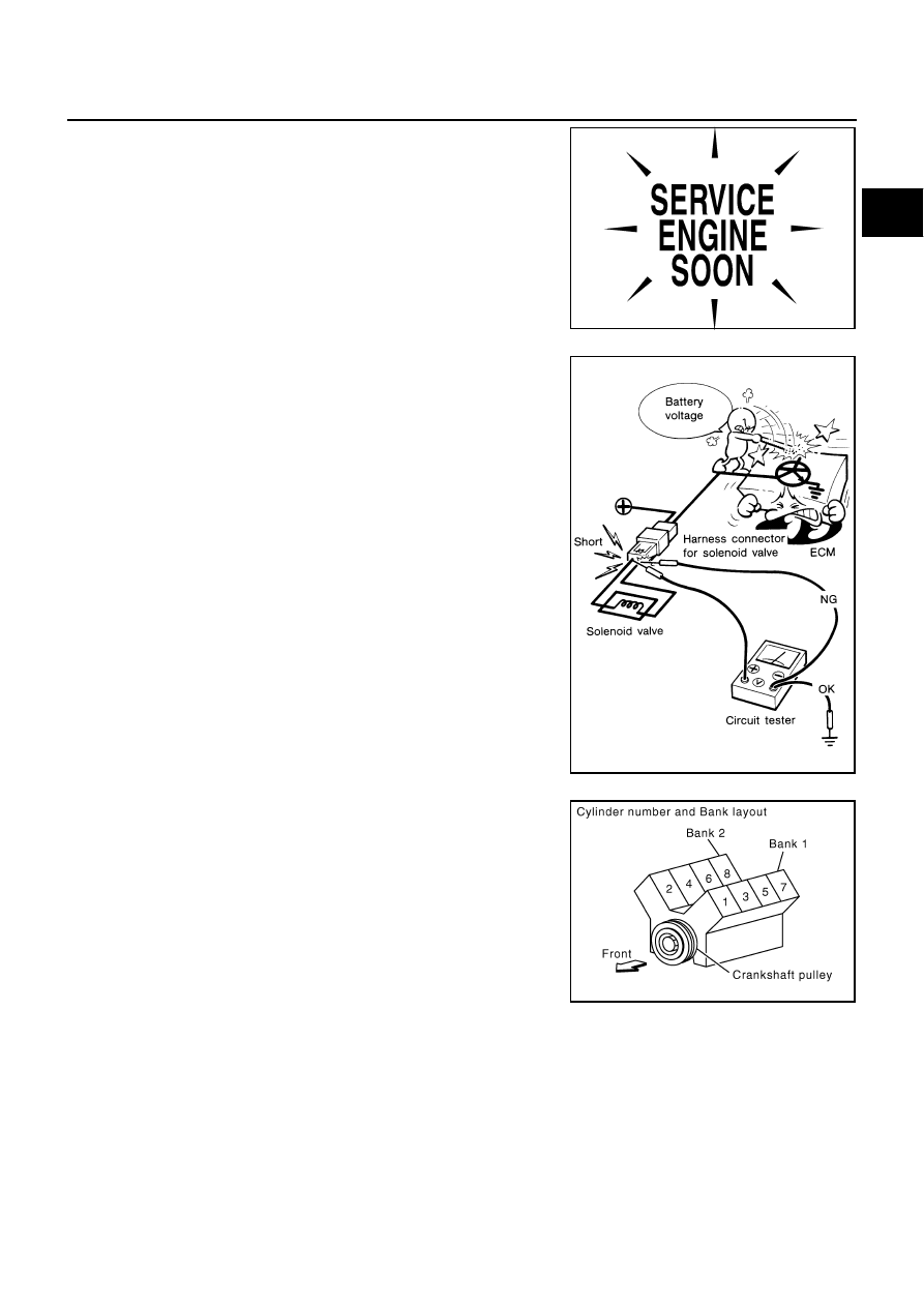
When measuring ECM signals with a circuit tester, never
allow the two tester probes to contact.
Accidental contact of probes will cause a short circuit and
damage the ECM power transistor.

Do not use ECM ground terminals when measuring input/
output voltage. Doing so may result in damage to the ECM's
transistor. Use a ground other than ECM terminals, such as
the ground.

B1 indicates the bank 1 and B2 indicates the bank 2 as
shown in the figure.

SEF217U

SEF348N

PBIB1144E

EC-20

PRECAUTIONS

Do not operate fuel pump when there is no fuel in lines.

Tighten fuel hose clamps to the specified torque.

Do not depress accelerator pedal when starting.

Immediately after starting, do not rev up engine unneces-
sarily.

Do not rev up engine just prior to shutdown.

When installing C.B. ham radio or a mobile phone, be sure
to observe the following as it may adversely affect elec-
tronic control systems depending on installation location.

Keep the antenna as far as possible from the electronic
control units.

Keep the antenna feeder line more than 20 cm (8 in) away
from the harness of electronic controls.
Do not let them run parallel for a long distance.

Adjust the antenna and feeder line so that the standing-
wave radio can be kept smaller.

Be sure to ground the radio to vehicle body.

PBIB2462E

SEF709Y

SEF708Y

PREPARATION

EC-21

C

D

E

F

G

H

I

J

K

L

M

A

EC

PREPARATION

PFP:00002

Special Service Tools

NBS001Q2

The actual shapes of Kent-Moore tools may differ from those of special service tools illustrated here.

Tool number
(Kent-Moore No.)
Tool name

Description

EG17650301
(J-33984-A)
Radiator cap tester 
adapter

Adapting radiator cap tester to radiator cap and 
radiator filler neck
a: 28 (1.10) dia.
b: 31.4 (1.236) dia.
c: 41.3 (1.626) dia.
Unit: mm (in)

KV10117100
(J-36471-A)
Heated oxygen 
sensor wrench

Loosening or tightening heated oxygen sensor 2 
with 22 mm (0.87 in) hexagon nut

KV10114400
(J-38365)
Heated oxygen 
sensor wrench

Loosening or tightening air fuel ratio sensor 1
a: 22 mm (0.87 in)

(J-44321)
Fuel pressure gauge 
kit

Checking fuel pressure

KV109E0010
(J-46209)
Break-out box

Measuring the ECM signals with a circuit tester

KV109E0080
(J-45819)
Y-cable adapter

Measuring the ECM signals with a circuit tester

S-NT564

S-NT379

S-NT636

LEC642

S-NT825

S-NT826

EC-22

PREPARATION

Commercial Service Tools

NBS001Q3

Tool name
(Kent-Moore No.)

Description

Leak detector
i.e.: (J-41416)

Locating the EVAP leak

EVAP service port 
adapter
i.e.: (J-41413-OBD)

Applying positive pressure through EVAP service 
port

Fuel filler cap adapter
i.e.: (MLR-8382)

Checking fuel tank vacuum relief valve opening 
pressure

Socket wrench

Removing and installing engine coolant 
temperature sensor

Oxygen sensor thread 
cleaner
i.e.: (J-43897-18)
(J-43897-12)

Reconditioning the exhaust system threads 
before installing a new oxygen sensor. Use with 
anti-seize lubricant shown below.
a: J-43897-18 18 mm diameter with pitch 1.5 
mm for Zirconia Oxygen Sensor
b: J-43897-12 12 mm diameter with pitch 1.25 
mm for Titania Oxygen Sensor

Anti-seize lubricant 

i.e.: (Permatex

TM


133AR or equivalent 
meeting MIL 
specification MIL-A-
907)

Lubricating oxygen sensor thread cleaning tool 
when reconditioning exhaust system threads.

S-NT703

S-NT704

S-NT815

S-NT705

AEM488

S-NT779


Content   ..  343  344  345  346   ..