Infiniti Q45. Manual - part 338


  Index      Infiniti     Infiniti Q45 - service repair manual 2006 year


Search            copyright infringement  


Content   ..  336  337  338  339   ..


Infiniti Q45. Manual - part 338


VOICE ACTIVATED CONTROL SYSTEM

DI-219

C

D

E

F

G

H

I

J

L

M

A

B

DI

2. 

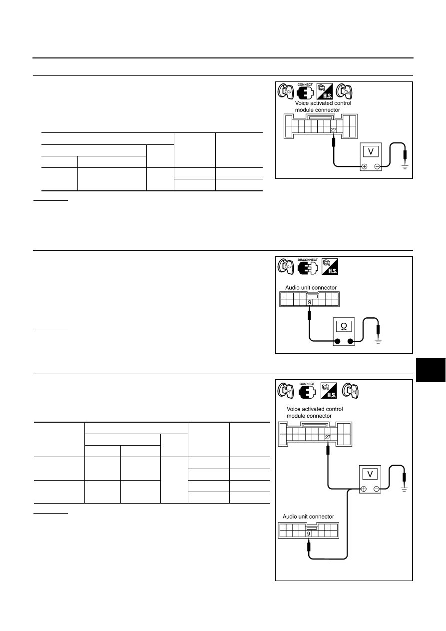
CHECK AUDIO UNIT MUTE SIGNAL 

1.

Connect voice activated control module connector and audio
unit connector.

2.

Turn ignition switch ON.

3.

Check voltage between voice activated control module harness
connector B69 terminal 27 and ground.

OK or NG

OK

>> Replace audio unit.

NG

>> Replace voice activated control module.

Audio Mute Not Released

NKS001EX

1. 

AUDIO UNIT MUTE SIGNAL CIRCUIT

1.

Turn ignition switch OFF.

2.

Disconnect voice activated control module connector and audio
unit connector.

3.

Check continuity between audio unit harness connector M87 ter-
minal 9 and ground.

OK or NG

OK

>> GO TO 2.

NG

>> Repair harness or connector.

2. 

CHECK MUTE SIGNAL

1.

Connect voice activated control module connector and audio
unit connector.

2.

Turn ignition switch ON.

3.

Check the following. 

OK or NG

OK

>> Replace audio unit.

NG

>> Replace voice activated control module.

Terminals

PTT switch 

condition

Voltage (V)

(+)

(–)

Connector

Terminal

B69

27

Ground

ON

Approx. 0

OFF

Approx. 5

PKIA9800E

9 – Ground

: Continuity should not exist.

PKIA9801E

Unit

Terminals

PTT switch 

condition

Voltage (V)

(+)

(–)

Connector

Terminal 

Voice activated 
control module

B69

27

Ground

ON

Approx. 0

OFF

Approx. 5

Audio unit

M87

9

ON

Approx. 0

OFF

Approx. 5

PKIA9802E

DI-220

VOICE ACTIVATED CONTROL SYSTEM

Removal and Installation for Voice Activated Control Module

NKS001EY

REMOVAL

1.

Remove trunk trim. Refer to 

EI-60, "TRUNK ROOM TRIM & TRUNK LID FINISHER"

 .

2.

Remove the bolts, and disconnect connectors.

3.

Remove voice activated control module.

4.

Remove bracket from voice activated control module.

INSTALLATION

Installation is the reverse order of removal.

Removal and Installation for Microphone

NKS002Q0

REMOVAL

1.

Remove map lamp cover. Refer to 

EI-58, "HEADLINING"

 .

2.

Remove the screw (A), and remove microphone (1).

INSTALLATION

Installation is the reverse order of removal.

SKIA0500E

SKIA0501E

PKIC4897E

COMPASS

DI-221

C

D

E

F

G

H

I

J

L

M

A

B

DI

COMPASS

PFP:24835

Precautions for Compass

NKS002JE

NOTE:

Do not install the ski rack, antenna, etc. which is attach to the vehicle with a magnet base. It affects the
operation of the compass.

When cleaning the mirror, use a paper towel or similar material dampened with glass cleaner. Do not
spray glass cleaner directly on the mirror as it may cause the liquid cleaner to enter the mirror housing.

System Description

NKS002JB

This electronic compass is able to display 8 primary directions:
N, NE, E, SE, S, SW, W, NW.

The inside mirror switch is used to operate the compass and
automatic anti-glare system.

Switch Operation

NOTE:
For further details of the compass and automatic anti-glare system, refer to Owner's Manual

All standard compasses determine direction relative to Magnetic North; however, this electronic compass
is designed to display direction relative to True North.

The difference between Magnetic North and True North varies from place to place across the surface of
the earth.

This electronic compass must be “told” approximately where it is on the earth’s surface so that the Mag-
netic North reading can be properly converted into a True North display.

To tell the electronic compass where it’s at, the earth is separated into numbered “Zone Variances”. The
Zone Variance number in which the compass is to function must be entered into this electronic compass.

Each zone is magnetically about 4.2

°

 wide. Typically, anything under 22.5

°

 total zone change is not

noticed on the electronic compass display. However, over 22.5

°

, a reading may be off by one or more pri-

mary directions.

On long trips, a vehicle may leave its original zone and enter one or more new zones. Generally, you do
not need to reset the compass zone if you travel between 3 or 4 zones, such as business travel or vaca-
tion. The typical driver will not notice any difference on the display within 3 or 4 zones. However, if the
vehicle is “permanently” moved to a new location, it is recommended that the compass zone be reset.

PKIC4899E

1.

Compass display

2.

Inside mirror switch

Press

Compass is turned ON/OFF

Press and hold
(for 3 – 6 sec.)

Automatic anti-glare system turns ON/OFF

Press and hold
(for 6 – 9 sec.)

Compass display turns to zone variation change 
mode

Press and hold
(for more than 9 sec.)

Compass display turns to calibration mode

DI-222

COMPASS

Troubleshooting

NKS002TZ

The electronic compass is highly protected from changes in most magnetic fields. However, some large
changes in magnetic fields can affect it. Some examples are (but not limited to): high tension power lines,
large steel buildings, subways, steel bridges, automatic car washes, large piles of scrap metal, etc. While
this does not happen very often, it is possible.

During normal operation, the Compass Mirror will continuously update the compass calibration to adjust
for gradual changes in the vehicle’s magnetic “remnant” field. If the vehicle is subjected to high magnetic
influences, the compass may appear to indicate false headings, become locked, or appear that it is
unable to be calibrated. If this occurs, perform the calibration procedure.

If at any time the compass continually displays the incorrect direction or the reading is erratic or locked,
verify the correct zone variance.

Troubleshooting Chart

Symptom

Cause

Solution / Reference

The compass display reads “C”.

Compass is not calibrated.

Incorrect zone variance setting.

Large change in magnetic field (Steel 
bridges, subways, concentrations of 
metal, carwashes, etc.)

Compass was calibrated incorrectly or in 
the presence of a strong magnetic field.

Perform Calibration.
Refer to 

DI-223, "Calibration Procedure"

 .

Compass shows the wrong direction.

Compass does not change direction – 
appears “Locked”.

Compass does not show all the directions, 
one or more is missing.

The compass was calibrated but it “loses” 
calibration.

On long trips the compass shows the 
wrong direction.

Perform Zone Variation Setting if correct 
reading is desired in that location.
Refer to 

DI-223, "Zone Variation Setting 

Procedure"

 .

Compass does not work – No direction is 
displayed.

Compass not turned ON.

Check for green LED indicator (inside mir-
ror switch).

No power to inside mirror.

Check power supply circuit. 


Content   ..  336  337  338  339   ..