Infiniti Q45. Manual - part 326


  Index      Infiniti     Infiniti Q45 - service repair manual 2006 year


Search            copyright infringement  


Content   ..  324  325  326  327   ..


Infiniti Q45. Manual - part 326


VEHICLE INFORMATION AND INTEGRATED SWITCH SYSTEM /WITH NAVIGA-

TION SYSTEM

DI-171

C

D

E

F

G

H

I

J

L

M

A

B

DI

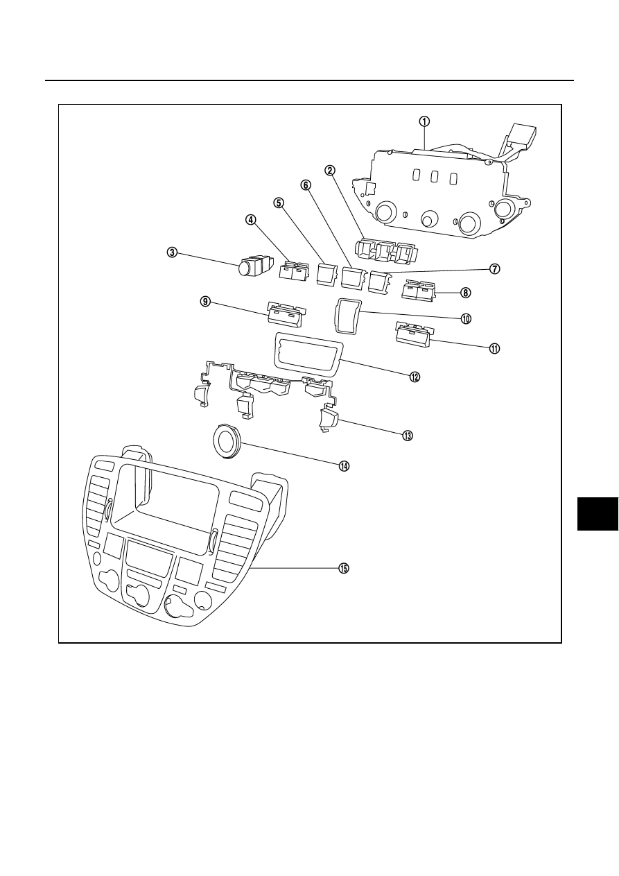
Disassembly and Assembly for Multifunction Switch

NKS001E0

DISASSEMBLY

1.

Remove the screws (7).

2.

Remove the switches.

ASSEMBLY

Assembly is the reverse order of disassembly.

1.

Multifunction switch

2.

Escutcheon

3.

Hazard switch

4.

Defroster, rear window defogger 
switch

5.

Function switch

6.

Function switch

7.

Function switch

8.

TAPE and DISC switch

9.

A/C switch

10. Escutcheon

11. Radio switch

12. Escutcheon

13. Switch assembly

14. Escutcheon

15. Cluster lid C

PKIC4896E

DI-172

REAR VIEW MONITOR

REAR VIEW MONITOR

PFP:28260

System Description

NKS001E1

The rear view monitor is equipped to check the backward of the vehicle with display when A/T selector
lever is in reverse position.

The lines of vehicle sides and the distance from the rear end of the vehicle are provided on display as a
guide. It allows the driver to know the distance between the vehicle and a backward object, and the width
of the vehicle much easier.

POWER SUPPLY AND GROUND

Power is supplied at all time

through 15A fuse [No. 52, located in fuse, fusible link and relay block (J/B)]

to rear view camera control unit terminal 1.

When ignition switch is ACC or ON position, power is supplied

through 10A fuse [No. 21, located in fuse block (J/B) No. 1]

to rear view camera control unit terminal 2.

When ignition switch is ON or START position, power is supplied

through 10A fuse [No. 9, located in fuse block (J/B) No. 1]

to back-up lamp relay terminals 2 and 5.

Ground is supplied 

to rear view camera control unit terminal 3

through grounds B217 and B256, 

to rear view camera terminal 2

through grounds B217 and B256.

REAR VIEW CAMERA OPERATION

AV control unit (AV and NAVI control unit) switches the display to rear view camera image when input reverse
signal by AV communication line.
Display shows image from rear view camera image and rear view camera guideline.

SKIB0699E

REAR VIEW MONITOR

DI-173

C

D

E

F

G

H

I

J

L

M

A

B

DI

Rear View Camera Image

When A/T selector lever is reverse position, power is supplied

through backup lamp relay terminal 1

to A/T assembly terminal 7.

Then back-up lamp relay is energized

from backup lamp relay terminal 3

to rear view camera control unit terminal 4.

Then, rear view camera control unit is sent camera ON signal

through rear view camera control unit terminal 8

to rear view camera terminal 1.

An image taken by rear view camera is sent

through rear view camera terminals 3 and 4

to rear view camera control unit terminals 10 and 9. 

Then an image is sent

through rear view camera control unit terminals 11 and 12

to display terminals 11 and 9.

Then composite synchronizing signal is sent

through rear view camera control unit terminal 14

to display terminal 10

for the display and the image.

An image of rear view will be projected on the display.

Rear View Camera Guide Line

When A/T selector lever is reverse position, power is supplied

through back-up lamp relay terminal 1

to A/T assembly terminal 7.

Then back-up lamp relay is energized

from back-up lamp relay terminal 3

to AV control unit terminal 19 (without NAVI)

to AV and NAVI control unit terminal 27 (with NAVI).

Then AV control unit (AV and NAVI control unit) is sent rear view camera guideline image

through AV control unit terminals 18, 21 and 24 (without NAVI)

through AV and NAVI control unit terminals 18, 21 and 15 (with NAVI)

to display terminals 1, 2 and 3.

Rear view camera guide line will be projected on the display.

DI-174

REAR VIEW MONITOR

Component Parts and Harness Connector Location

NKS001E2

SKIB0700E


Content   ..  324  325  326  327   ..