Infiniti Q45. Manual - part 306
LANE DEPARTURE WARNING SYSTEM
DI-91
C
D
E
F
G
H
I
J
L
M
A
B
DI
SYMPTOM CHART
Power Supply and Ground Circuit Inspection
NKS002C2
1.
CHECK FUSE
Check for blown LDW camera unit fuse.
OK or NG
OK
>> GO TO 2.
NG
>> Be sure to eliminate cause of malfunction before installing new fuse. Refer to
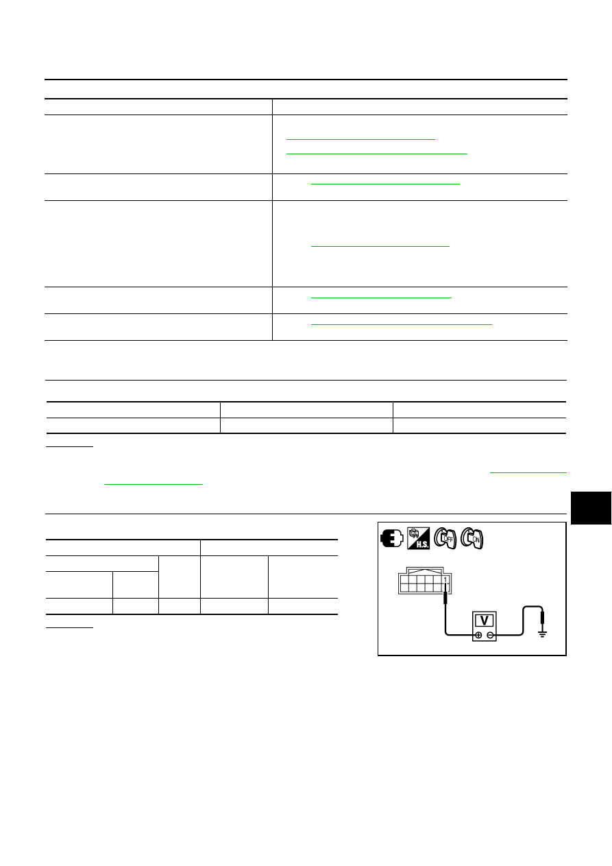
2.
CHECK POWER SUPPLY CIRCUIT
Check voltage between LDW camera unit and ground.
OK or NG
OK
>> GO TO 3.
NG
>> Repair harness between LDW camera unit and fuse.
Symptom
Diagnosis/Service procedure
LDW system is not activated.
(LDW system ON indicator turns ON/OFF.)
Perform the following inspections.
1.
DI-93, "LDW Chime Circuit Inspection"
2.
DI-97, "LDW Indicator Lamp Circuit Inspection"
Replace LDW camera unit, found normal function in the above inspections.
LDW system does not turn ON/OFF.
(LDW system ON indicator does not turn ON/OFF.)
Perform
DI-94, "LDW Switch Circuit Inspection"
Replace LDW camera unit, found normal function in the above inspection.
Warning functions are untimely.
(Example)
●
Warning does not function when driving on lane mark-
ers.
●
Warning functions when driving in a lane.
●
Differs position from actual condition functions.
Perform
DI-74, "Camera Aiming Adjustment"
Functions when changing the course to the turn signal
direction.
Perform
DI-98, "Turn Signal Input Inspection"
Replace LDW camera unit, found normal function in the above inspection.
LDW indicator lamp does not illuminate with ignition
switch ON.
Perform
DI-97, "LDW Indicator Lamp Circuit Inspection"
Replace LDW camera unit, found normal function in the above inspection.
Unit
Power source
Fuse No.
LDW camera unit
Ignition switch ON or START
1
Terminals
Ignition switch position
(+)
(–)
OFF
ON
LDW camera
unit connector
Terminal
R26
1
Ground
0 V
Battery voltage
PKIC0246E