Infiniti Q45. Manual - part 295


  Index      Infiniti     Infiniti Q45 - service repair manual 2006 year


Search            copyright infringement  


Content   ..  293  294  295  296   ..


Infiniti Q45. Manual - part 295


WARNING LAMPS

DI-47

C

D

E

F

G

H

I

J

L

M

A

B

DI

Rear Door Switch Inspection

NKS001BW

1. 

CHECK REAR DOOR SWITCH OPERATION
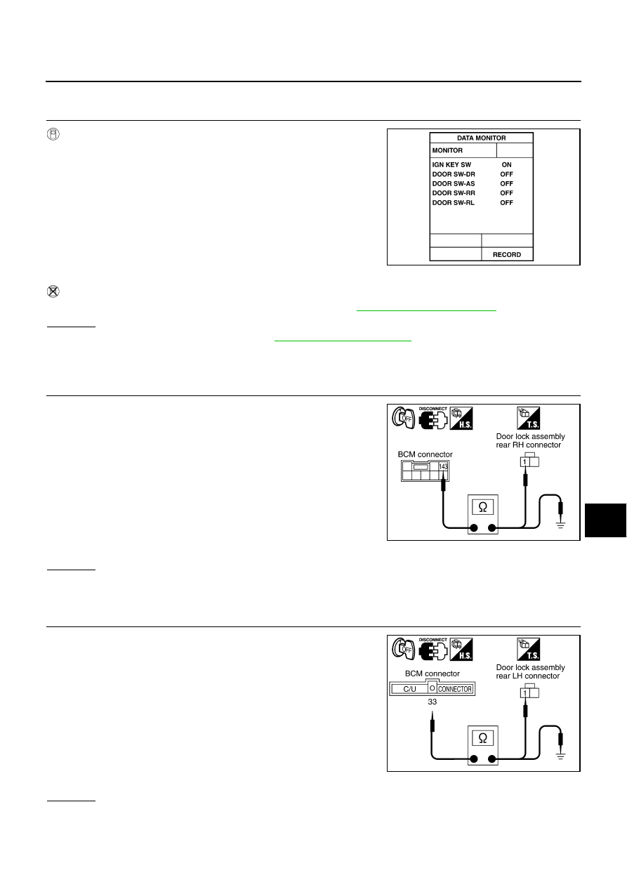
With CONSULT-II

Check rear door switch “DOOR SW” in “DATA MONITOR” mode
with CONSULT-II.

Without CONSULT-II

Check rear door switches in switch monitor mode. Refer to 

DI-43, "On Board Diagnosis"

 .

OK or NG

OK

>> Rear door switch is OK. Return to 

DI-44, "SYMPTOM CHART"

 .

NG 1: Rear door switch RH signal is irregular.>>GO TO 2.
NG 2: Rear door switch LH signal is irregular.>>GO TO 3.

2. 

CHECK REAR DOOR SWITCH (RH) CIRCUIT

1.

Turn ignition switch OFF.

2.

Disconnect BCM connector and door lock assembly rear RH
(door switch) connector.

3.

Check continuity between BCM harness connector B4 terminal
143 and door lock assembly rear RH (door switch) harness con-
nector D82 terminal 1.

4.

Check continuity between BCM harness connector B4 terminal
143 and ground.

OK or NG

OK

>> GO TO 4.

NG

>> Repair harness or connector.

3. 

CHECK REAR DOOR SWITCH (LH) CIRCUIT

1.

Turn ignition switch OFF.

2.

Disconnect BCM connector and door lock assembly rear LH
(door switch) connector.

3.

Check continuity between BCM harness connector M4 terminal
33 and door lock assembly rear LH (door switch) harness con-
nector D62 terminal 1.

4.

Check continuity between BCM harness connector M4 terminal
33 and ground.

OK or NG

OK

>> GO TO 4.

NG

>> Repair harness or connector.

“DOOR SW-RR”

When rear door RH is open

: ON

When rear door RH is closed

: OFF

“DOOR SW-RL”

When rear door LH is open

: ON

When rear door LH is closed

: OFF

SKIB0682E

143 – 1

: Continuity should exist.

143 – Ground

: Continuity should not exist.

SKIB1009E

33 – 1

: Continuity should exist.

33 – Ground

: Continuity should not exist.

SKIB0684E

DI-48

WARNING LAMPS

4. 

CHECK REAR DOOR SWITCH

Check continuity between door lock assembly rear (door switch)
connector D62 or D82 terminals 1 and 2.

OK or NG

OK

>> GO TO 5.

NG

>> Replace door lock assembly rear (door switch).

5. 

CHECK REAR DOOR SWITCH GROUND CIRCUIT

Check continuity between door lock assembly rear (door switch) har-
ness connector D62 or D82 terminal 2 and ground.

OK or NG

OK

>> Replace BCM.

NG

>> Check ground harness.

Electrical Components Inspection

NKS001BX

OIL PRESSURE SWITCH

Check continuity between the oil pressure switch and ground.

FRONT DOOR SWITCH

Check continuity between terminal 1 and door switch case ground.

1 – 2

When rear door is open

: Continuity should exist.

When rear door is close

: Continuity should not exist.

SKIB0685E

2 – Ground

: Continuity should exist.

SKIB0686E

Condition

Oil pressure kPa (kg/cm

2

 , psi)

Continuity

Engine stopped

Less than 29 (0.3, 4)

Yes

Engine running

More than 29 (0.3, 4)

No

ELF0044D

terminal

Condition

Continuity

1

Door switch 
case ground

When door switch is released

Yes

When door switch is pressed

No

SKIB0442E

A/T INDICATOR

DI-49

C

D

E

F

G

H

I

J

L

M

A

B

DI

A/T INDICATOR

PFP:24814

Wiring Diagram — AT/IND —

NKS001BY

TKWM1551E

DI-50

A/T INDICATOR

A/T Indicator Does Not Illuminate

NKS001BZ

1. 

CHECK OPERATION OF A/T INDICATOR SEGMENT

Activate self-diagnosis mode of combination meter. Refer to 

DI-16, "Self-Diagnosis Mode of Combination

Meter"

 .

Are all A/T indicator segments displayed?

YES

>> GO TO 2.

NO

>> Replace combination meter.

2. 

CHECK TCM SYSTEM

Perform TCM self-diagnosis. Refer to 

AT-85, "CONSULT-II Function (A/T)"

  in AT section.

OK or NG

OK

>> Replace combination meter.

NG

>> Perform “Diagnosis Procedure” for displayed DTC.


Content   ..  293  294  295  296   ..